Advertisement
2753 Michigan Road • Madison, Indiana 47250 • 855-743-3427
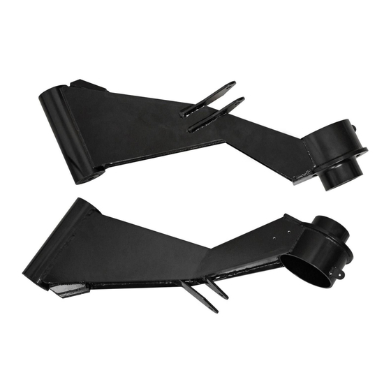
Item
Description
A
Trailing Arm, Passenger
B
Trailing Arm, Driver
C
CV Guard Brackets
D
Brake Line Clips
E
CV Guard Clips
Need help with your installation?
sales@superatv.com
1-855-743-3427
© 2014 SuperATV.com. All Rights Reserved.
Trailing Arms:
Qty
1
2
2
2
2
B
(kit contents continue on following page)
www.superatv.com
8:00am - 9:00pm EST M-Th
8:00am - 7:00pm EST Friday
9:00am - 2:00pm EST Saturday
Installation INSTRUCTIONS
C
Read instructions and view illustrations before beginning.
Thank You
for Can-Am Commander
D
A
For Choosing
Rev IN-RTA-CA-COM-4 2/9/2016
E
Advertisement
Table of Contents

Subscribe to Our Youtube Channel
Related Manuals for SuperATV RTA-CA-COM-4


Summary of Contents for SuperATV RTA-CA-COM-4
- Page 1 Need help with your installation? Read instructions and view illustrations before beginning. Thank You sales@superatv.com www.superatv.com For Choosing 8:00am - 9:00pm EST M-Th 1-855-743-3427 8:00am - 7:00pm EST Friday 9:00am - 2:00pm EST Saturday © 2014 SuperATV.com. All Rights Reserved. Rev IN-RTA-CA-COM-4 2/9/2016...
- Page 2 The Buyer is also responsible to obey all ® applicable federal, state, and local laws and ordinances when operating his/her vehicle while using this product, and the Buyer agrees to hold SuperATV harmless from any ®...
- Page 3 Removal: Keep all components removed from machine. Remove: Unbolt Sway Bar from Trailing Arms - Shocks from Trailing Arms and remove from machine. - Caliper and Rotor (right side) - Hubs - Axles - Trailing Arms from Frame (Driver Side) (Hub) (Driver Side) IN-RTA-CA-COM...
- Page 4 - Install new Axle. - Set Adjustment Bearing position and install Trailing Arm (A) or (B) to Frame with stock hardware. new Axle stock hardware (driver side) (driver side) Adjustment Bearing SuperATV recommends setting Adjustments Bearings to position shown as starting point IN-RTA-CA-COM...
- Page 5 Installation continued: - Reinstall Sway Bar to Trailing Arm with hardware shown. - Reinstall Shock to Trailing Arm with stock hardware. - Repeat steps for opposite side. - Reinstall Rotors, Calipers, and Hubs. - SEE FOLLOWING PAGE: Reroute Passenger Side Brake Line. Install Brakeline Clips (D) to Brake Line and secure to Trailing Arm (A) with hardware shown.
- Page 6 - Remove Bracket from Stud. - Pass Caliper through location Brake Caliper through here. shown. Brake Line may need Brake Line may need to be removed. removal. Caliper will now be Remove Bracket under Frame. from Stud - Route to Spindle and secure Caliper.
- Page 7 Installation continued: - Install CV Guard Clips (E) to Trailing Arms (A)(B) with hardware shown. - Install CV Guard Brackets (C) to Trailing Arms (A)(B) with hardware shown. - Install stock CV Guards as shown. M5 x 16mm - Set camber. See last page. CV Guard here M5 Nut M5 Washer...
- Page 8 Rear Camber Adjustment: loosen Trailing Arm hardware (passenger side) use provided wrench to make adjustments Trailing Arm, Passenger (A) shown off machine for clarity Bearing in this position provides Bearing in this position provides positive camber (tire out at top) negative camber (tire in at top) IN-RTA-CA-COM...
Need help?
Do you have a question about the RTA-CA-COM-4 and is the answer not in the manual?
Questions and answers