Table of Contents
Advertisement
Quick Links
2753 Michigan Road • Madison, Indiana 47250 • 855-743-3427
(disregard any remaining hardware)
2x
#8-18 x 3/16" Lg. Screw
2x
#8-18 x 3/4" Lg. Screw
4x
M5-.80 x 16mm Lg. BHCS
4x
M5-.80 Nylock Nut
4x
M8-1.25 x 20mm Lg. FHCS
4x
M8-1.25 Nylock Nut
Components may be installed in locations other than where shown. Alway verify wire harness length.
Need help with your installation?
sales@superatv.com
1-855-743-3427
®
© 2018 SuperATV.com
. All Rights Reserved.
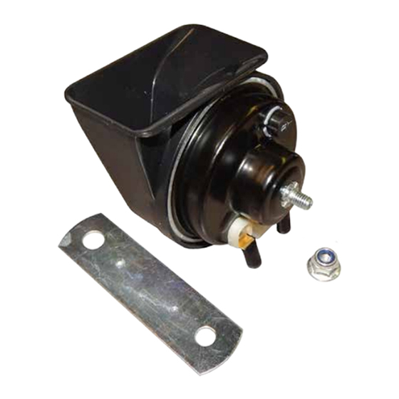
Horn Kit
www.superatv.com
8:00am - 9:00pm EST M-Th
8:00am - 7:00pm EST Friday
9:00am - 2:00pm EST Saturday
INSTALLATION INSTRUCTIONS
Plug and Play Turn Signal Kit:
for Can-Am Defender
Mounting Bracket
Control Box Bracket
Hazard Light Switch
Wire Ties
4x - LED Signal
Read instructions and view illustrations before beginning.
Turn Signal Switch
Horn Switch
Thank You
For Choosing
IN-TSK-CA-DEF-004 10/29/2018
Advertisement
Table of Contents

Subscribe to Our Youtube Channel
Related Manuals for SuperATV TSK-CA-DEF-004


Summary of Contents for SuperATV TSK-CA-DEF-004
- Page 1 Need help with your installation? Read instructions and view illustrations before beginning. Thank You sales@superatv.com www.superatv.com For Choosing 8:00am - 9:00pm EST M-Th 1-855-743-3427 8:00am - 7:00pm EST Friday 9:00am - 2:00pm EST Saturday ® © 2018 SuperATV.com . All Rights Reserved. IN-TSK-CA-DEF-004 10/29/2018...
- Page 3 - Remove Front Bulkhead Cover. Front Bulkhead Cover (passenger) - Remove Battery Cover. Battery Cover (passenger) - Remove Floor Cover. Floor Cover (passenger) IN-TSK-CA-DEF-004...
- Page 4 - Secure Control Box to Bracket with provided M5 hardware. Control Box Bracket Control Box - Join Control Box Bracket and Mounting Bracket with provided M8 hardware; do not tighten completely. provided M8 hardware Mounting Bracket IN-TSK-CA-DEF-004...
-
Page 5: Wiring Harness
Wiring Harness: - Route Harness to Front and Rear of vehicle. (passenger) Harness to FRONT FRONT Harness to REAR IN-TSK-CA-DEF-004... -
Page 6: Power Connections
Power Connections: connect 12V and Ground wires from Harness to Accessory Power Block (driver footwell looking under Dash) Accessory Power Block Black (-) Red (+) IN-TSK-CA-DEF-004... - Page 7 Horn: - User may install Horn in location different than shown. - Location must be protected from mud, debris, and water. - Illustration is SuperATV’s choice. drill Ø1/4” hole - Connect Harness and install Horn. - Secure with Nut provided in Horn Kit. Horn Kit IN-TSK-CA-DEF-004...
-
Page 8: Led Signal
- Plug LED Signals into corresponding inputs on Front Harness. - Secure all Wires as needed. (passenger) LED Signal LED Signal If Light is hard to insert separate as shown. Gasket - Separate LED from Gasket. - Install Gasket into hole. - Install LED into Gasket. IN-TSK-CA-DEF-004... - Page 9 - Remove Tail Lights. remove remove stock Seal from Tail Light (driver) IN-TSK-CA-DEF-004...
- Page 10 - Raise Cargo Bed and unplug stock harness in location shown. Stock Rear Harness connection is located on, and under, passenger side Frame Rail (driver) - Connect Rear Harness to stock Harness, as shown, and route to Tail Lights. - Secure all Wires as needed. Stock Rear Harness (passenger) IN-TSK-CA-DEF-004...
-
Page 11: Switch Orientation
Switch Orientation TERMINAL 7 AND ARROW MUST BE ORIENTED AS SHOWN Rotate Actuator 180° - Gently pry one side up. - Pry opposite up and remove Actuator. - Rotate and snap Actuator into place. Actuator IN-TSK-CA-DEF-004... -
Page 12: Switch Mounting
Switch Mounting: - User may install Switches in locations different than shown. - Verify that Wire Harness will reach Switches before mounting. SuperATV recommends testing Switches before permanently mounting. use stock locations if available use stock locations if available if no stock locations are availabe, use provided template and cut slots for Switch mounting... - Page 13 - Install Mounting Bracket to Frame with provided M8 hardware; tighten completely. provided M8 hardware Mounting Bracket - Reinstall stock components. IN-TSK-CA-DEF-004...
- Page 14 Use of this product on public streets, roads, or highways may be in violation law. The Buyer is solely and exclusively legally and personally responsible for any violation of the law by the installation or use of this product. In no case will SuperATV be held liable if Buyer violates the law or uses ®...
Need help?
Do you have a question about the TSK-CA-DEF-004 and is the answer not in the manual?
Questions and answers