Advertisement
Table of Contents
2753 Michigan Road • Madison, Indiana 47250 • 855-743-3427
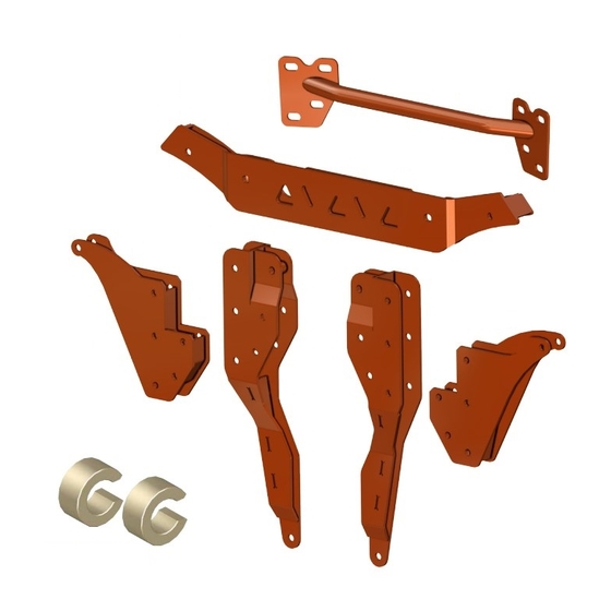
Item
Description
A
Rear Shock Bracket Brace
B
Front Shock Bracket
C
Rear Shock Bracket x 2
D
Shock Bracket Base, Right
E
Shock Bracket Base, Left
(Passenger)
Steering Stop Kit
Need help with your installation?
sales@superatv.com
1-855-743-3427
®
© 2016 SuperATV.com
. All Rights Reserved.
C
www.superatv.com
8:00am - 8:00pm EST M-Th
8:00am - 7:00pm EST Friday
9:00am - 2:00pm EST Saturday
INSTALLATION INSTRUCTIONS
3" Lift Kit:
B
D
E
Read instructions and view illustrations before beginning.
for Polaris
General™
®
A
C
Thank You
For Choosing
Rev IN-LK-P-GEN1K-3 9/19/2019
(Driver)
Advertisement
Table of Contents

Related Manuals for SuperATV 3 inch Lift Kit


Summary of Contents for SuperATV 3 inch Lift Kit
- Page 1 Read instructions and view illustrations before beginning. Thank You sales@superatv.com www.superatv.com For Choosing 8:00am - 8:00pm EST M-Th 1-855-743-3427 8:00am - 7:00pm EST Friday 9:00am - 2:00pm EST Saturday ® © 2016 SuperATV.com . All Rights Reserved. Rev IN-LK-P-GEN1K-3 9/19/2019...
- Page 2 The Buyer is also responsible to obey all ® applicable federal, state, and local laws and ordinances when operating his/her vehicle while using this product, and the Buyer agrees to hold SuperATV harmless from any ®...
-
Page 3: Wire Harness
Wire Harness’: - Remove Wire Harness’ from Shock Mount and components. - Reroute and connect after Front Bracket has been installed. (Passenger Side) IN-LK-P-GEN1K-3... -
Page 4: Shock Mount
Vent Tube: (Passenger Side) (Driver Side) Shock Mount Front Remove Vent Tube from Shock Mount and reroute Vent Tube away from Shock Mount IN-LK-P-GEN1K-3... - Page 5 Rear components shown must be removed; Keep all components removed from machine. Shocks remove rearmost hardware only from Lower A-Arms (Driver Side) IN-LK-P-GEN1K-3...
- Page 6 If present, relocate Relay. (Driver Side) Rear remove Relay; discard hardware cut wire-tie Relay Reinstall Relay to location shown with provided self-tapping screw. Wire-tie Harness so that no interference can occur. IN-LK-P-GEN1K-3...
- Page 7 Remove any previously installed Steering Stops. Provided Steering Stops must be installed. Steering Stop Installation: Rack and Pinion shown off machine for clarity Note: Driver Side installation is shown. - Install Bushing onto Rack and Pinion shaft; repeat for opposite side. - Reinstall Boots to Rack and Pinion.
-
Page 8: Rear Installation
Rear Installation: Do not tighten hardware completely until last step. - Install Shock Bracket Base, Left (E) into stock Shock Mount with stock Shock hardware. (Driver Side) Secure Shock Bracket Base, Left (E) here stock Shock hardware Rear Rear (Driver Side) - Install hardware shown to rear portion of Lower A-Arms;... - Page 9 Rear Installation continued: - Insert Rear Shock Bracket Brace (A) through Frame from opposite side. - Install Shock Bracket (C) into Shock Bracket Base, Left (E). - Secure Shock Bracket (C), Shock Bracket Base, Left (E), and Rear Shock Bracket Brace (A) with hardware shown.
-
Page 10: Front Installation
Front Installation: Do not tighten hardware completely until last step. - Install Front Lift Bracket (B) to Shock Mount with hardware shown. - Reinstall Shocks with stock hardware. M10 x 70mm (Driver Side) (Triangles towards Front) Front (Passenger Side) M10 Nut (Driver Side) Front Stock Polaris Front Shocks must be re-installed upside down from how they were...
Need help?
Do you have a question about the 3 inch Lift Kit and is the answer not in the manual?
Questions and answers