Bradley WF2613 Installation Instructions Manual
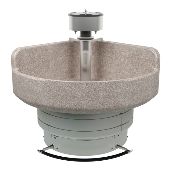
Classic corner 54" washfountain with foot control
Hide thumbs
Also See for WF2613:
- Installation manual (22 pages) ,
- Installation manual (27 pages) ,
- Installation manual (24 pages)
Table of Contents
Advertisement
Quick Links
IMPORTANT
Read this entire installation manual
to ensure proper installation.
Flush all the water supply lines
before making connections.
Main water supply to the unit
should be ON at all times.
This installation manual and parts
list should be filed by the owner's
maintenance department.
215-609 Rev. J; EN 06-915B
© 2007 Bradley Corporation
Page 1 of 26
4/6/2007
Installation
Instructions
WF2613
Classic Corner 54"
Washfountain with Foot
Control
Table of Contents
Pre-Installation Information . . . . . . . . . . . . . . . . . 2
Semi-Circular Washfountain Dimensions . . . . . . . 3
Rough-In Specifications . . . . . . . . . . . . . . . . . . . 4-5
Drain Rough-In Specifications . . . . . . . . . . . . . . . .6
Pedestal Assembly and Drain Spud Installation . .7-8
Supplies w/Optional Soap Dispenser (A/O drains) . . . . .9-10
Supplies w/Optional Soap Dispenser (B/H drains) . . . .11-12
Valve Assembly . . . . . . . . . . . . . . . . . . . . . . . . . .13
Installing the Operating Rod . . . . . . . . . . . . . . . .14
Soap Recommendations and Maintenance . . . . . .15
Check Valve Troubleshooting . . . . . . . . . . . . . . .15
Soap Valve Repair Parts . . . . . . . . . . . . . . . . . . . .16
Stop, Strainer and Check Valve Repair Parts . . . .17
Sprayhead Troubleshooting/Repair Parts . . . . . . 18
Foot Valve Breakdown and Repair Kit . . . . . . . .19
Manual Mixing Valve Repair Parts . . . . . . . . . . .20
Angle Volume Control Valve Repair Parts . . . . . .21
Vernatherm™ Mixing Valve Maintenance . . .22-24
Cleaning and Maintenance Instructions . . . . .25-26
UPC Certified
P.O. Box 309, Menomonee Falls, WI 53052-0309
TEL. 1-800-BRADLEY
http://www.bradleycorp.com
U P
C
C
R
FAX 262-251-5817
Advertisement
Chapters
Table of Contents
Troubleshooting

Related Manuals for Bradley WF2613


Summary of Contents for Bradley WF2613
- Page 1 This installation manual and parts list should be filed by the owner’s maintenance department. P.O. Box 309, Menomonee Falls, WI 53052-0309 TEL. 1-800-BRADLEY FAX 262-251-5817 215-609 Rev. J; EN 06-915B © 2007 Bradley Corporation http://www.bradleycorp.com Page 1 of 26 4/6/2007...
- Page 2 Installation Instructions Pre-Installation Information Operation The system used on your Bradley Foot Controlled Washfountain actuates the valve when the foot rail is depressed. The valve then stays open until the foot rail is released. Supplies Required: • (6) lag bolts, screws or other fasteners to anchor washfountain pedestal to floor.
- Page 3 NOTE: Drain must be connected with 2" schedule 40 welded wrought iron pipe, minimum, to provide lower support for this installation. Vent or support pipe must be of the same material in 1-1/2". Bradley Corporation • 215-609 Rev. J; EN 06-915B 4/6/2007...
- Page 4 Rough-In Specifications Rough-In Notes: 1. All pipes and fittings not furnished by Bradley are shown in broken lines. 2. Supply lines for one to two washfountains should be 1"; for three washfountains 1-1/4"; for more than three washfountains, pipe sizes should be increased proportionately.
- Page 5 11-1/4" to 13-1/4" 9-1/4" to 10-1/4" 6" to 11" 6" to 8-1/2" interfere with diagonal frame 286mm to 337mm 235mm to 260mm 152mm to 279mm 152mm to 216mm member on pedestal). Bradley Corporation • 215-609 Rev. J; EN 06-915B 4/6/2007...
- Page 6 2. Assemble the drain to the dimension shown in Figure 1 or Figure 2. NOTE: All piping shown in dotted lines to be supplied by the installer. (mm) Vented Trap (111-024) Types A and O Types B and H Figure 1 Figure 2 4/6/2007 Bradley Corporation • 215-609 Rev. J; EN 06-915B...
- Page 7 4 Attach the spacers, foot rail and spring pins to the foot valve levers (the bend in the center of the foot rail must be pointing up) (see Figures 3 and 5). Diagonal Support (194-043) STD Hgt. (194-043A) JUV. Hgt. Figure 3 Figure 4 Figure 5 Bradley Corporation • 215-609 Rev. J; EN 06-915B 4/6/2007...
- Page 8 5. Tighten the spud and locknut against the bowl (see Figure 7). SPUD 112-015 (Terrazzo) STRAINER 112-016 (Bradstone (S45-067) and Stainless Steel) BOWL LOCKNUT (161-021) WASHER (142-068) Figure 6 Figure 7 4/6/2007 Bradley Corporation • 215-609 Rev. J; EN 06-915B...
- Page 9 (see Figure 8). 2. Continue installation with Step 5 on Page 13. Bradley Corporation • 215-609 Rev. J; EN 06-915B 4/6/2007...
- Page 10 Lower Tie Bar (159-009) Tie Rod Nut (110-064) & Set Screws (See Figure 10 on page 13 (160-208) for valving assembly) Operating Rod (S14-007, Std. Ht.) (S14-007A, Juv. Ht.) COLD Figure 8 4/6/2007 Bradley Corporation • 215-609 Rev. J; EN 06-915B...
- Page 11 . Connect the Vent Pipe a. Connect the vent pipe to the vent through the ceiling with the pipe union. b. Continue installation with Step 5 on Page 13. Bradley Corporation • 215-609 Rev. J; EN 06-915B 4/6/2007...
- Page 12 (S57-005, 54") Sprayhead (S05-054C) Sprayhead Supply Pipe (3/8") Gasket (125-011) Vented Trap (111-024) (See Figure 10 on page 13 for valving assembly) Operating Rod (S14-007, Std. Ht.) (S14-007A, Juv. Ht.) Figure 9 4/6/2007 Bradley Corporation • 215-609 Rev. J; EN 06-915B...
- Page 13 Model Type A Type B Type O Type H Standard Height 9" (229mm) 6-3/16 (157mm) 9" (229mm) 6-3/16 (157mm) Juvenile Height 5-1/4" (133mm) 3-7/16 (87mm) 5-1/4" (133mm) 3-7/16 (87mm) Table 1 Bradley Corporation • 215-609 Rev. J; EN 06-915B 4/6/2007...
- Page 14 Spray should not be set closer than 2" to the side of the bowl. 6. Install pedestal panels by fastening panels to pedestal legs with the Phillips head machine screws supplied. Figure 12 4/6/2007 Bradley Corporation • 215-609 Rev. J; EN 06-915B...
- Page 15 Soap thickness is determined by a measurement called viscosity. Soap viscosity should be between 100 cps (centerpoise) and 2500 cps for all Bradley soap dispensers. Thinner soaps are perceived by the users as being “watered down” so users tend to take more than they need, resulting in waste. Thick soaps flow slower and inhibit the “flushing”...
- Page 16 To change from liquid to powdered, the plug must be removed. If none is present, it will be necessary to drill out the bearing hole with a 1/2" or 5/8" drill. The plastic container configuration forms a natural template for locating the bearing hole. 4/6/2007 Bradley Corporation • 215-609 Rev. J; EN 06-915B...
- Page 17 Tail Piece - Plated 110-005 Tail Piece Nut - Brass 110-005A Tail Piece Nut - Plated 124-001AF Tail Piece Washer 135-001AB Spring S21-015 Check Assembly S45-050 Repair Kit Includes these parts Bradley Corporation • 215-609 Rev. J; EN 06-915B 4/6/2007...
- Page 18 Neoprene Washer-Top 139-031 Sprayhead Manifold — 124-001AL Washer 160-211 Carriage Bolt 115-061 Sprayhead Top — 116-008 Sprayhead Bottom — 124-001AT Washer 161-025 124-020E Sprayhead Grommet - Corner — 125-001DF Neoprene Washer-Bottom 4/6/2007 Bradley Corporation • 215-609 Rev. J; EN 06-915B...
- Page 19 QTY. PART NO. DESCRIPTION 118-300 HOUSING 135-088 SPRING 125-154 O-RING, #2-127 S64-093 PLUNGER ASSEMBLY 117-016 VALVE SEAT 125-001Y DIAPHRAGM 124-001V WASHER, 1-3/8" x 5/8" 130-033 KEY, VALVE SEAT S45-125 LUBRICANT (not shown) Bradley Corporation • 215-609 Rev. J; EN 06-915B 4/6/2007...
- Page 20 — — 110-005 Tailpiece Nut - Brass — — 129-007A Tailpiece - Chrome — — — 110-005A Tailpiece Nut - Chrome — — — 124-001AF Tailpiece Washer — Parts not shown 4/6/2007 Bradley Corporation • 215-609 Rev. J; EN 06-915B...
- Page 21 S45-198 Item Part No. Description 125-001BC O-Ring 152-038 Roll Pin 121-016 Bonnet 121-016A Bonnet — — 124-001BD Fiber Washer 119-060 Valve Core 118-033 Valve Body — 118-033B Valve Body — — Bradley Corporation • 215-609 Rev. J; EN 06-915B 4/6/2007...
- Page 22 3. Shut the cold water inlet off by closing the cold water stop-strainer-check valve. While the cold water supply is off, check to make sure that the hot water flow has shut down. TEMPERATURE TEMPERATURE ADJUSTMENT LOCKING STEM Figure 13 4/6/2007 Bradley Corporation • 215-609 Rev. J; EN 06-915B...
- Page 23 2. Place thermostat into container with 115° F water. The pushrod should pop out of the thermostat approximately 1/10". 3. If thermostat pushrod does not pop out, the thermostat must be replaced. Contact your Bradley representative and ask for Repair Kit (part number S65-259).
- Page 24 Parts List S65-259 Valve Repair Kit Nut 3/8-24 Hex Jam Item Part No. Description S39-413 Thermostat 125-001BX O-Ring 125-157 O-Ring O-Ring O-Ring Stem Thermostat Piston Spring Seal Cup Valve Body Figure 14 4/6/2007 Bradley Corporation • 215-609 Rev. J; EN 06-915B...
- Page 25 Clean terrazzo washfountain bowls daily or as often as conditions require with any standard household detergent, hot water and soft cloth. Bradley terrazzo bowls may be refurbished by cleaning with tri-sodium phosphate, two pounds per gallon, and a scrub brush. Stubborn spots may be removed with emery cloth.
- Page 26 It is emphasized that all products should be used in strict accordance with package instructions. 4/6/2007 Bradley Corporation • 215-609 Rev. J; EN 06-915B...
-
Page 27: Table Of Contents
This installation manual and parts list should be filed by the owner’s maintenance department. P.O. Box 309, Menomonee Falls, WI 53052-0309 215-1451 Rev. D; EN 06-915B TEL. 1-800-BRADLEY FAX 262-251-5817 © 2007 Bradley Corporation http://www.bradleycorp.com Page 1 of 27 4/6/2007... -
Page 28: Pre-Installation Information
• 1" hot and cold water supply lines and fittings (refer to rough-ins on pages 4-5). • Reducing fittings and 1/2" nominal copper tubing for models with supplies from above. • Standard P-trap (refer to rough-ins on pages 4-5). Vented trap supplied by Bradley when required. -
Page 29: Corner Washfountain Dimensions
NOTE: Drain must be connected with 2" schedule 40 welded wrought iron pipe, minimum, to provide lower support for this installation. Vent or support pipe must be of the same material in 1-1/2". Bradley Corporation • 215-1451 Rev. D; EN 06-915B 4/6/2007... -
Page 30: Rough-In Specifications
Rough-In Specifications Rough-In Notes: 1. All pipes and fittings not furnished by Bradley are shown in broken lines. 2. Supply lines for one to two washfountains should be 1"; for three washfountains 1-1/4"; for more than three washfountains, pipe sizes should be increased proportionately. - Page 31 11-1/4" to 13-1/4" 9-1/4" to 10-1/4" 6" to 11" 6" to 8-1/2" interfere with diagonal frame 286mm to 337mm 235mm to 260mm 152mm to 279mm 152mm to 216mm member on pedestal). Bradley Corporation • 215-1451 Rev. D; EN 06-915B 4/6/2007...
- Page 32 2. Assemble the drain to the dimension shown in Figure 1 or Figure 2. NOTE: All piping shown in dotted lines to be supplied by the installer. (mm) Vented Trap (111-024) Types A and O Types B and H Figure 1 Figure 2 4/6/2007 Bradley Corporation • 215-1451 Rev. D; EN 06-915B...
-
Page 33: Assembling The Pedestal
2. Attach the pedestal frame members, the rear support members and the rear legs with the 5/16" stove bolts and nuts provided (see Figure 3). Diagonal Support (194-043) STD Hgt. (194-043A) JUV. Hgt. Figure 3 Bradley Corporation • 215-1451 Rev. D; EN 06-915B 4/6/2007... -
Page 34: Anchoring The Pedestal To The Floor
5. Tighten the spud and locknut against the bowl (see Figure 5). SPUD 112-015 (Terrazzo) STRAINER 112-016 (Bradstone (S45-067) and Stainless Steel) BOWL LOCKNUT (161-021) WASHER (142-068) Figure 4 Figure 5 4/6/2007 Bradley Corporation • 215-1451 Rev. D; EN 06-915B... - Page 35 • If connector leaks, reseat tubing according to above procedure. If leaking persists, replace male connector, or call your Bradley representative for assistance. 4. Place sprayhead with 1/2" tubing onto support tube as shown in Figure 7. Run tubing down through support tube.
- Page 36 LOWER TIE BAR (159-009) (159-009) TIE ROD HEX NUT TIE ROD HEX NUT (See Figure 9b on page 14 (110-064) (110-064) for valving assembly) SET SCREW SET SCREW Figure 7 (160-208) (160-208) COLD 4/6/2007 Bradley Corporation • 215-1451 Rev. D; EN 06-915B...
- Page 37 • If connector leaks, reseat tubing according to above procedure. If leaking persists, replace male connector, or call your Bradley representative for assistance. 3. Place sprayhead with 1/2" tubing onto support tube as shown in Figure 8. Run tubing down through support tube.
- Page 38 SUPPORT TUBE SUPPORT TUBE (S57-005) (S57-005) SUPPORT TUBE GASKET SUPPORT TUBE GASKET (125-011) (125-011) VENTED TRAP VENTED TRAP (111-024) (111-024) (See Figure 9b on page 14 for valving assembly) Figure 8 4/6/2007 Bradley Corporation • 215-1451 Rev. D; EN 06-915B...
-
Page 39: Installing The Valve Assembly
4. Turn the water supply on and check for leaks and adequate water flow. Replace the access panels on both sides of the washfountain. Module Cover Assembly (S04-112) IR Module Assembly (S83-040) Sensor Bracket (140-718) Sensor (S83-039) Window Figure 9a (269-832) Bradley Corporation • 215-1451 Rev. D; EN 06-915B 4/6/2007... - Page 40 DISTANCE FROM 1/2" SUPPLY TO FINISHED FLOOR Model Type A Type B Type O Type H Standard Height 9" (229mm) 6-3/16 (157mm) 9" (229mm) 6-3/16 (157mm) Juvenile Height 5-1/4" (133mm) 3-7/16 (87mm) 5-1/4" (133mm) 3-7/16 (87mm) 4/6/2007 Bradley Corporation • 215-1451 Rev. D; EN 06-915B...
-
Page 41: Soap Recommendations And Maintenance
Soap thickness is determined by a measurement called viscosity. Soap viscosity should be between 100 cps (centerpoise) and 2500 cps for all Bradley soap dispensers. Thinner soaps are perceived by the users as being “watered down” so users tend to take more than they need, resulting in waste. Thick soaps flow slower and inhibit the “flushing”... - Page 42 To change from liquid to powdered, the plug must be removed. If none is present, it will be necessary to drill out the bearing hole with a 1/2" or 5/8" drill. The plastic container configuration forms a natural template for locating the bearing hole. 4/6/2007 Bradley Corporation • 215-1451 Rev. D; EN 06-915B...
-
Page 43: Solenoid Valve Troubleshooting
1. Turn off water supplies to fixture. 2. Inspect check valves for proper installation. 3. Open the stops and clean the strainers, if necessary. 4. Inspect mixing valve for proper installation (see Vernatherm valve on page 23). Bradley Corporation • 215-1451 Rev. D; EN 06-915B 4/6/2007... - Page 44 Corner Washfountain with Infrared Control WF2613 Installation Instructions Solenoid Valve S08-055 Repair Parts SOLENOID VALVE SPRING (S27-250) (269-578) ARMATURE (269-577) REPAIR KIT (S65-155) DIAPHRAGM (269-1346) REDUCING COUPLING (269-1246) MALE CONNECTOR (269-626) 4/6/2007 Bradley Corporation • 215-1451 Rev. D; EN 06-915B...
- Page 45 Tail Piece - Plated 110-005 Tail Piece Nut - Brass 110-005A Tail Piece Nut - Plated 124-001AF Tail Piece Washer 135-001AB Spring S21-015 Check Assembly S45-050 Repair Kit Includes these parts Bradley Corporation • 215-1451 Rev. D; EN 06-915B 4/6/2007...
- Page 46 Neoprene Washer-Top 139-031 Sprayhead Manifold — 124-001AL Washer 160-211 Carriage Bolt 115-061 Sprayhead Top — 116-008 Sprayhead Bottom — 124-001AT Washer 161-025 124-020E Sprayhead Grommet - Corner — 125-001DF Neoprene Washer-Bottom 4/6/2007 Bradley Corporation • 215-1451 Rev. D; EN 06-915B...
- Page 47 — — 110-005 Tailpiece Nut - Brass — — 129-007A Tailpiece - Chrome — — — 110-005A Tailpiece Nut - Chrome — — — 124-001AF Tailpiece Washer — Parts not shown Bradley Corporation • 215-1451 Rev. D; EN 06-915B 4/6/2007...
- Page 48 S45-198 Item Part No. Description 125-001BC O-Ring 152-038 Roll Pin 121-016 Bonnet 121-016A Bonnet — — 124-001BD Fiber Washer 119-060 Valve Core 118-033 Valve Body — 118-033B Valve Body — — 4/6/2007 Bradley Corporation • 215-1451 Rev. D; EN 06-915B...
- Page 49 3. Shut the cold water inlet off by closing the cold water stop-strainer-check valve. While the cold water supply is off, check to make sure that the hot water flow has shut down. TEMPERATURE TEMPERATURE ADJUSTMENT LOCKING STEM Figure 10 Bradley Corporation • 215-1451 Rev. D; EN 06-915B 4/6/2007...
- Page 50 2. Place thermostat into container with 115° F water. The pushrod should pop out of the thermostat approximately 1/10". 3. If thermostat pushrod does not pop out, the thermostat must be replaced. Contact your Bradley representative and ask for Repair Kit (part number S65-259).
- Page 51 Parts List S65-259 Valve Repair Kit Nut 3/8-24 Hex Jam Item Part No. Description S39-413 Thermostat 125-001BX O-Ring 125-157 O-Ring O-Ring O-Ring Stem Thermostat Piston Spring Seal Cup Valve Body Figure 11 Bradley Corporation • 215-1451 Rev. D; EN 06-915B 4/6/2007...
- Page 52 Clean terrazzo washfountain bowls daily or as often as conditions require with any standard household detergent, hot water and soft cloth. Bradley terrazzo bowls may be refurbished by cleaning with tri-sodium phosphate, two pounds per gallon, and a scrub brush. Stubborn spots may be removed with emery cloth.
- Page 53 It is emphasized that all products should be used in strict accordance with package instructions. Bradley Corporation • 215-1451 Rev. D; EN 06-915B 4/6/2007...
- Page 54 This installation manual and parts list should be filed by the owner’s maintenance department. 215-1520 Rev. D; EN 06-915B P.O. Box 309, Menomonee Falls, WI 53052-0309 © 2007 Bradley Corporation TEL. 1-800-BRADLEY FAX 262-251-5817 Page 1 of 29 4/6/2007 http://www.bradleycorp.com...
-
Page 55: Pre-Installation Information
• 1" hot and cold water supply lines and fittings (refer to rough-ins on pages 4-5). • Reducing fittings and 1/2" nominal copper tubing for models with supplies from above. • Standard P-trap (refer to rough-ins on pages 4-5). Vented trap supplied by Bradley when required. -
Page 56: Corner Washfountain Dimensions
NOTE: Drain must be connected with 2" schedule 40 welded wrought iron pipe, minimum, to provide lower support for this installation. Vent or support pipe must be of the same material in 1-1/2". Bradley Corporation • 215-1520 Rev. D; EN 06-915B 4/6/2007... -
Page 57: Rough-In Specifications
Rough-In Specifications Rough-In Notes: 1. All pipes and fittings not furnished by Bradley are shown in broken lines. 2. Supply lines for one to two washfountains should be 1"; for three washfountains 1-1/4"; for more than three washfountains, pipe sizes should be increased proportionately. - Page 58 11-1/4" to 13-1/4" 9-1/4" to 10-1/4" 6" to 11" 6" to 8-1/2" interfere with diagonal frame 286mm to 337mm 235mm to 260mm 152mm to 279mm 152mm to 216mm member on pedestal). Bradley Corporation • 215-1520 Rev. D; EN 06-915B 4/6/2007...
- Page 59 2. Assemble the drain to the dimension shown in Figure 1 or Figure 2. NOTE: All piping shown in dotted lines to be supplied by the installer. (mm) Vented Trap (111-024) Types A and O Types B and H Figure 1 Figure 2 4/6/2007 Bradley Corporation • 215-1520 Rev. D; EN 06-915B...
-
Page 60: Assembling The Pedestal
2. Attach the pedestal frame members, the rear support members and the rear legs with the 5/16" stove bolts and nuts provided (see Figure 3). Diagonal Support (194-043) STD Hgt. (194-043A) JUV. Hgt. Figure 3 Bradley Corporation • 215-1520 Rev. D; EN 06-915B 4/6/2007... -
Page 61: Anchoring The Pedestal To The Floor
5. Tighten the spud and locknut against the bowl (see Figure 5). SPUD 112-015 (Terrazzo) STRAINER 112-016 (Bradstone (S45-067) and Stainless Steel) BOWL LOCKNUT (161-021) WASHER (142-068) Figure 4 Figure 5 4/6/2007 Bradley Corporation • 215-1520 Rev. D; EN 06-915B... - Page 62 • If connector leaks, reseat tubing according to above procedure. If leaking persists, replace male connector, or call your Bradley representative for assistance. 4. Place sprayhead with 1/2" tubing onto support tube as shown in Figure 7. Run tubing down through support tube.
- Page 63 LOWER TIE BAR (159-009) (159-009) TIE ROD HEX NUT TIE ROD HEX NUT Figure 7 (See Figure 9 on page 13 (110-064) (110-064) for valving assembly) SET SCREW SET SCREW (160-208) (160-208) COLD 4/6/2007 Bradley Corporation • 215-1520 Rev. D; EN 06-915B...
- Page 64 • If connector leaks, reseat tubing according to above procedure. If leaking persists, replace male connector, or call your Bradley representative for assistance. 3. Place sprayhead with 1/2" tubing onto support tube as shown in Figure 8. Run tubing down through support tube.
- Page 65 SUPPORT TUBE SUPPORT TUBE (S57-005) (S57-005) SUPPORT TUBE GASKET SUPPORT TUBE GASKET (125-011) (125-011) VENTED TRAP VENTED TRAP (111-024) (111-024) (See Figure 9 on page 13 for valving assembly) Figure 8 4/6/2007 Bradley Corporation • 215-1520 Rev. D; EN 06-915B...
- Page 66 DISTANCE FROM 1/2" SUPPLY TO FINISHED FLOOR Model Type A Type B Type O Type H Standard Height 9" (229mm) 6-3/16 (157mm) 9" (229mm) 6-3/16 (157mm) Juvenile Height 5-1/4" (133mm) 3-7/16 (87mm) 5-1/4" (133mm) 3-7/16 (87mm) Bradley Corporation • 215-1520 Rev. D; EN 06-915B 4/6/2007...
-
Page 67: Electrical Connections For Touch Time
5. If the switch does not activate water, recheck electrical connections to the terminal block. Touch Time Module (S83-180) Corner TT Module Assembly Transformer (S83-134) Supply Tube 1/2" Supply To 1/2" Supply Manual Mixing Valve (S01-038) Figure 10 TMA Optional (S01-525) 4/6/2007 Bradley Corporation • 215-1520 Rev. D; EN 06-915B... -
Page 68: Troubleshooting
If, after checking the transformer, the solenoid valve and the wiring, you are unable to activate the sprayhead by pressing the Touch Time push button, the Touch Time switch assembly is not working properly and needs to be replaced. Contact your Bradley representative to order a replacement switch assembly. - Page 69 Standard Equipment) (129-007) (110-005) Manual Mixing Valve (S01-038) Washer (124-001AF) Touch Time™ Module Assembly (S83-180) MODULE COVER (ONLY) MODULE COVER (ONLY) (S04-113) (S04-113) SWITCH SWITCH TOUCH TIME TOUCH TIME (S83-139B) (S83-139B) 4/6/2007 Bradley Corporation • 215-1520 Rev. D; EN 06-915B...
- Page 70 Tail Piece - Plated 110-005 Tail Piece Nut - Brass 110-005A Tail Piece Nut - Plated 124-001AF Tail Piece Washer 135-001AB Spring S21-015 Check Assembly S45-050 Repair Kit Includes these parts Bradley Corporation • 215-1520 Rev. D; EN 06-915B 4/6/2007...
-
Page 71: Check Valve Troubleshooting
1. Turn off water supplies to fixture. 2. Inspect check valves for proper installation. 3. Open the stops and clean the strainers, if necessary. 4. Inspect mixing valve for proper installation (see Vernatherm valve on page 25) 4/6/2007 Bradley Corporation • 215-1520 Rev. D; EN 06-915B... -
Page 72: Solenoid Valve Repair Parts
Corner Washfountain with Touch Time™ Control Installation Instructions WF2613 Solenoid Valve Repair Parts SOLENOID VALVE SPRING (S27-250) (269-578) ARMATURE (269-577) REPAIR KIT (S65-155) DIAPHRAGM (269-1346) REDUCING COUPLING (269-1246) MALE CONNECTOR (269-626) Bradley Corporation • 215-1520 Rev. D; EN 06-915B 4/6/2007... -
Page 73: Soap Recommendations And Maintenance
Soap thickness is determined by a measurement called viscosity. Soap viscosity should be between 100 cps (centerpoise) and 2500 cps for all Bradley soap dispensers. Thinner soaps are perceived by the users as being “watered down” so users tend to take more than they need, resulting in waste. Thick soaps flow slower and inhibit the “flushing”... - Page 74 To change from liquid to powdered, the plug must be removed. If none is present, it will be necessary to drill out the bearing hole with a 1/2" or 5/8" drill. The plastic container configuration forms a natural template for locating the bearing hole. Bradley Corporation • 215-1520 Rev. D; EN 06-915B 4/6/2007...
-
Page 75: Sprayhead Troubleshooting/Repair Parts
Neoprene Washer-Top 139-031 Sprayhead Manifold — 124-001AL Washer 160-211 Carriage Bolt 115-061 Sprayhead Top — 116-008 Sprayhead Bottom — 124-001AT Washer 161-025 124-020E Sprayhead Grommet - Corner — 125-001DF Neoprene Washer-Bottom 4/6/2007 Bradley Corporation • 215-1520 Rev. D; EN 06-915B... -
Page 76: Manual Mixing Valve Repair Parts
— — 110-005 Tailpiece Nut - Brass — — 129-007A Tailpiece - Chrome — — — 110-005A Tailpiece Nut - Chrome — — — 124-001AF Tailpiece Washer — Parts not shown Bradley Corporation • 215-1520 Rev. D; EN 06-915B 4/6/2007... - Page 77 S45-198 Item Part No. Description 125-001BC O-Ring 152-038 Roll Pin 121-016 Bonnet 121-016A Bonnet — — 124-001BD Fiber Washer 119-060 Valve Core 118-033 Valve Body — 118-033B Valve Body — — 4/6/2007 Bradley Corporation • 215-1520 Rev. D; EN 06-915B...
- Page 78 3. Shut the cold water inlet off by closing the cold water stop-strainer-check valve. While the cold water supply is off, check to make sure that the hot water flow has shut down. TEMPERATURE TEMPERATURE ADJUSTMENT LOCKING STEM Figure 11 Bradley Corporation • 215-1520 Rev. D; EN 06-915B 4/6/2007...
- Page 79 2. Place thermostat into container with 115° F water. The pushrod should pop out of the thermostat approximately 1/10". 3. If thermostat pushrod does not pop out, the thermostat must be replaced. Contact your Bradley representative and ask for Repair Kit (part number S65-259).
- Page 80 Parts List S65-259 Valve Repair Kit Nut 3/8-24 Hex Jam Item Part No. Description S39-413 Thermostat 125-001BX O-Ring 125-157 O-Ring O-Ring O-Ring Stem Thermostat Piston Spring Seal Cup Valve Body Figure 12 Bradley Corporation • 215-1520 Rev. D; EN 06-915B 4/6/2007...
- Page 81 Clean terrazzo washfountain bowls daily or as often as conditions require with any standard household detergent, hot water and soft cloth. Bradley terrazzo bowls may be refurbished by cleaning with tri-sodium phosphate, two pounds per gallon, and a scrub brush. Stubborn spots may be removed with emery cloth.
-
Page 82: Cleaning And Maintenance Instructions
It is emphasized that all products should be used in strict accordance with package instructions. Bradley Corporation • 215-1520 Rev. D; EN 06-915B 4/6/2007... -
Page 83: Soap Valve Repair Parts
This installation manual and parts list should be filed by the owner’s UPC Certified maintenance department. 215-1523 Rev. E; EN 06-915B P.O. Box 309, Menomonee Falls, WI 53052-0309 © 2007 Bradley Corporation TEL. 1-800-BRADLEY FAX 262-251-5817 Page 1 of 28 4/6/2007 http://www.bradleycorp.com... -
Page 84: Pre-Installation Information
• 1" hot and cold water supply lines and fittings (refer to rough-ins on pages 4-5). • Reducing fittings and 1/2" nominal copper tubing for models with supplies from above. • Standard P-trap (refer to rough-ins on pages 4-5). Vented trap supplied by Bradley when required. -
Page 85: Corner Washfountain Dimensions
NOTE: Drain must be connected with 2" schedule 40 welded wrought iron pipe, minimum, to provide lower support for this installation. Vent or support pipe must be of the same material in 1-1/2". Bradley Corporation • 215-1523 Rev. E; EN 06-915B 4/6/2007... -
Page 86: Rough-In Specifications
Rough-In Specifications Rough-In Notes: 1. All pipes and fittings not furnished by Bradley are shown in broken lines. 2. Supply lines for one to two washfountains should be 1"; for three washfountains 1-1/4"; for more than three washfountains, pipe sizes should be increased proportionately. - Page 87 11-1/4" to 13-1/4" 9-1/4" to 10-1/4" 6" to 11" 6" to 8-1/2" interfere with diagonal frame 286mm to 337mm 235mm to 260mm 152mm to 279mm 152mm to 216mm member on pedestal). Bradley Corporation • 215-1523 Rev. E; EN 06-915B 4/6/2007...
- Page 88 2. Assemble the drain to the dimension shown in Figure 1 or Figure 2. NOTE: All piping shown in dotted lines to be supplied by the installer. (mm) Vented Trap (111-024) Types A and O Types B and H Figure 1 Figure 2 Bradley Corporation • 215-1523 Rev. E; EN 06-915B 4/6/2007...
-
Page 89: Assembling The Pedestal
2. Attach the pedestal frame members, the rear support members and the rear legs with the 5/16" stove bolts and nuts provided (see Figure 3). Diagonal Support (194-043) STD Hgt. (194-043A) JUV. Hgt. Figure 3 Bradley Corporation • 215-1523 Rev. E; EN 06-915B 4/6/2007... -
Page 90: Anchoring The Pedestal To The Floor
5. Tighten the spud and locknut against the bowl (see Figure 5). SPUD 112-015 (Terrazzo) STRAINER 112-016 (Bradstone (S45-067) and Stainless Steel) BOWL LOCKNUT (161-021) WASHER (142-068) Figure 4 Figure 5 Bradley Corporation • 215-1523 Rev. E; EN 06-915B 4/6/2007... - Page 91 • If connector leaks, reseat tubing according to above procedure. If leaking persists, replace male connector, or call your Bradley representative for assistance. 4. Place sprayhead with 1/2" tubing onto support tube as shown in Figure 7. Run tubing down through support tube.
- Page 92 LOWER TIE BAR (159-009) (159-009) TIE ROD HEX NUT TIE ROD HEX NUT (See Figure 9 on page 13 (110-064) (110-064) for valving assembly) SET SCREW SET SCREW (160-208) (160-208) Figure 7 COLD Bradley Corporation • 215-1523 Rev. E; EN 06-915B 4/6/2007...
- Page 93 • If connector leaks, reseat tubing according to above procedure. If leaking persists, replace male connector, or call your Bradley representative for assistance. 3. Place sprayhead with 1/2" tubing onto support tube as shown in Figure 8. Run tubing down through support tube.
- Page 94 SUPPORT TUBE SUPPORT TUBE (S57-005) (S57-005) SUPPORT TUBE GASKET SUPPORT TUBE GASKET (125-011) (125-011) VENTED TRAP VENTED TRAP (111-024) (111-024) Figure 8 (See Figure 9 on page 13 for valving assembly) Bradley Corporation • 215-1523 Rev. E; EN 06-915B 4/6/2007...
- Page 95 DISTANCE FROM 1/2" SUPPLY TO FINISHED FLOOR Model Type A Type B Type O Type H Standard Height 9" (229mm) 6-3/16 (157mm) 9" (229mm) 6-3/16 (157mm) Juvenile Height 5-1/4" (133mm) 3-7/16 (87mm) 5-1/4" (133mm) 3-7/16 (87mm) Bradley Corporation • 215-1523 Rev. E; EN 06-915B 4/6/2007...
-
Page 96: Adjust The Air Valve Metering Time
2. Continue to adjust the timer until it is set at the desired length. 3. Replace the filter cap. RELEASE BUTTON 1/8” TUBING LOCKING SLOPE SEALING RING GRIPPING RIDGE TUBE STOP Figure 10 Figure 11 Bradley Corporation • 215-1523 Rev. E; EN 06-915B 4/6/2007... -
Page 97: Air Valve Troubleshooting
1. Turn off water supplies to fixture. 2. Inspect check valves for proper installation. 3. Open the stops and clean the strainers, if necessary. 4. Inspect mixing valve for proper installation (see Vernatherm valve on page 24). Bradley Corporation • 215-1523 Rev. E; EN 06-915B 4/6/2007... -
Page 98: Air Valve Repair Kits And Parts List
(Note: This repair kit also includes kit S65-110) LOCKWASHER 142-002CR SCREW 160-313 Air Valve Module Assembly (S65-134) MODULE COVER (ONLY) MODULE COVER (ONLY) (S04-113) (S04-113) PUSHBUTTON PUSHBUTTON (SEE NEXT PAGE) (SEE NEXT PAGE) Bradley Corporation • 215-1523 Rev. E; EN 06-915B 4/6/2007... - Page 99 Spring * (135-065) Duckbill Check * (198-010) Screw (160-165) Actuator Body * (118-279) Pushbutton Straight Tube Connector * (169-890) Assembly (S08-324) Nut (110-115) Actuator Bracket (140-743) * Included in Actuator Assembly S65-168 Bradley Corporation • 215-1523 Rev. E; EN 06-915B 4/6/2007...
- Page 100 Tail Piece - Plated 110-005 Tail Piece Nut - Brass 110-005A Tail Piece Nut - Plated 124-001AF Tail Piece Washer 135-001AB Spring S21-015 Check Assembly S45-050 Repair Kit Includes these parts Bradley Corporation • 215-1523 Rev. E; EN 06-915B 4/6/2007...
-
Page 101: Soap Recommendations And Maintenance
Soap thickness is determined by a measurement called viscosity. Soap viscosity should be between 100 cps (centerpoise) and 2500 cps for all Bradley soap dispensers. Thinner soaps are perceived by the users as being “watered down” so users tend to take more than they need, resulting in waste. Thick soaps flow slower and inhibit the “flushing”... - Page 102 To change from liquid to powdered, the plug must be removed. If none is present, it will be necessary to drill out the bearing hole with a 1/2" or 5/8" drill. The plastic container configuration forms a natural template for locating the bearing hole. Bradley Corporation • 215-1523 Rev. E; EN 06-915B 4/6/2007...
- Page 103 Neoprene Washer-Top 139-031 Sprayhead Manifold — 124-001AL Washer 160-211 Carriage Bolt 115-061 Sprayhead Top — 116-008 Sprayhead Bottom — 124-001AT Washer 161-025 124-020E Sprayhead Grommet - Corner — 125-001DF Neoprene Washer-Bottom Bradley Corporation • 215-1523 Rev. E; EN 06-915B 4/6/2007...
- Page 104 — — 110-005 Tailpiece Nut - Brass — — 129-007A Tailpiece - Chrome — — — 110-005A Tailpiece Nut - Chrome — — — 124-001AF Tailpiece Washer — Parts not shown Bradley Corporation • 215-1523 Rev. E; EN 06-915B 4/6/2007...
- Page 105 S45-198 Item Part No. Description 125-001BC O-Ring 152-038 Roll Pin 121-016 Bonnet 121-016A Bonnet — — 124-001BD Fiber Washer 119-060 Valve Core 118-033 Valve Body — 118-033B Valve Body — — Bradley Corporation • 215-1523 Rev. E; EN 06-915B 4/6/2007...
- Page 106 3. Shut the cold water inlet off by closing the cold water stop-strainer-check valve. While the cold water supply is off, check to make sure that the hot water flow has shut down. TEMPERATURE TEMPERATURE ADJUSTMENT LOCKING STEM Figure 12 Bradley Corporation • 215-1523 Rev. E; EN 06-915B 4/6/2007...
- Page 107 2. Place thermostat into container with 115° F water. The pushrod should pop out of the thermostat approximately 1/10". 3. If thermostat pushrod does not pop out, the thermostat must be replaced. Contact your Bradley representative and ask for Repair Kit (part number S65-259).
- Page 108 Parts List S65-259 Valve Repair Kit Nut 3/8-24 Hex Jam Item Part No. Description S39-413 Thermostat 125-001BX O-Ring 125-157 O-Ring O-Ring O-Ring Stem Thermostat Piston Spring Seal Cup Valve Body Figure 13 Bradley Corporation • 215-1523 Rev. E; EN 06-915B 4/6/2007...
- Page 109 Clean terrazzo washfountain bowls daily or as often as conditions require with any standard household detergent, hot water and soft cloth. Bradley terrazzo bowls may be refurbished by cleaning with tri-sodium phosphate, two pounds per gallon, and a scrub brush. Stubborn spots may be removed with emery cloth.
- Page 110 It is emphasized that all products should be used in strict accordance with package instructions. Bradley Corporation • 215-1523 Rev. E; EN 06-915B 4/6/2007...
Need help?
Do you have a question about the WF2613 and is the answer not in the manual?
Questions and answers