Advertisement
Quick Links
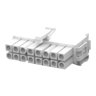
Vertical Pin Header
Printed Circuit (PC)
Board (Ref)
WIRE
SIZE RANGE
INSULATION DIAMETER
(AWG)
RANGE (mm [in.])
30-26
1.52 [.060] (Max)
26-22
1.19-1.75 [.047-.069]
22-18 or (2) 22
1.50-2.79 [.059-.110]
20-16
2.01-3.20 [.079-.126]
1. INTRODUCTION
This instruction sheet provides assembly and
disassembly procedures for Mini-Universal
MATE-N-LOK 2 connectors used in free hanging or
pc board applications.
Dimensions in this instruction sheet are in metric
NOTE
units [with U.S. customary units in brackets].
Figures are not drawn to scale.
i
Reasons for reissue of this instruction sheet are
provided in Section 6, REVISION SUMMARY.
2. DESCRIPTION
(See Figure 1)
The pin header is available in vertical and right-angle
configurations. The plug housing and cap housing
© 2012 Tyco Electronics Corporation, a TE Connectivity Ltd. company
All Rights Reserved
*Trademark
TE Connectivity, TE connectivity (logo), and TE (logo) are trademarks. Other logos, product and/or company names may be trademarks of their respective owners.
Mini-Universal MATE-N-LOK* 2
Connectors
Right-Angle Pin Header
Wires
(Ref)
STRIP
794216-1
794216-3
794218-1
794218-3
794220-1
794220-3
794222-1
794222-3
TOOLING ASSISTANCE CENTER 1-800-722-1111
PRODUCT INFORMATION 1-800-522-6752
Locking
Latch
Plug Housing
Cap Housing
Locking
Tab
CONTACT
PIN
LOOSE PIECE
794224-1
794224-3
794226-1
794226-3
794228-1
794228-3
794230-1
794230-3
Figure 1
accept the contacts listed in Figure 1. The housings
are polarized for proper alignment when mating. Keying
plugs are available to provide additional polarization
when mating the connectors. Positive locking features
prevent accidental disengagement of mated connectors.
3. ASSEMBLY PROCEDURE
3.1. Inserting Contacts
1. Select the appropriate pin and socket contacts
from Figure 1. Terminate the contacts according to
Application Specification 114-1111.
2. Rotate the wire end (back) of the housing 180
degrees along the pivot track until the first tooth of
each latching arm engages — the housing is in the
open position. See Figure 2.
This controlled document is subject to change.
For latest revision and Regional Customer Service,
visit our website at www.te.com
Instruction Sheet
408-3393
20 JUN 12 Rev B
Wires
(Ref)
Latching
Ear
Latching
Arm
SOCKET
STRIP
LOOSE PIECE
794217-1
794225-1
794217-3
794225-3
794219-1
794227-1
794219-3
794227-3
794221-1
794229-1
794221-3
794229-3
794223-1
794231-1
794221-3
794231-3
1 of 3
Advertisement

Related Manuals for TE Connectivity MATE-N-LOK 2 794216-1


Summary of Contents for TE Connectivity MATE-N-LOK 2 794216-1
- Page 1 All Rights Reserved PRODUCT INFORMATION 1-800-522-6752 For latest revision and Regional Customer Service, *Trademark visit our website at www.te.com TE Connectivity, TE connectivity (logo), and TE (logo) are trademarks. Other logos, product and/or company names may be trademarks of their respective owners.
- Page 2 408-3393 The wire end of the housing must be in the open Contact Insertion CAUTION position before inserting the contacts. Housing Cone Fingers (Not Engaged) Contact Contact Cavity First Tooth Push Latching Arm Wire End of Housing Contact Housing in Insulation Barrel Open Position...
- Page 3 408-3393 1. Deflect the latching ears one at a time, then Connector Mating lightly pull the wire end of the housing away from Locking Latch and the housing until the first tooth of the latching arms Locking Tab Engaged engage. See Figure 7. ...