Unitronics Samba OPLC SM43-J-R20 Installation Manual
Hide thumbs
Also See for Samba OPLC SM43-J-R20:
- Installation manual (12 pages) ,
- Installation manual (9 pages)
Advertisement
Чтобы подобрать подходящую модель, уточнить стоимость и срок поставки обращайтесь к нашим
специалистам по электронной почте i@sp-t.ru или по телефонам +7(499)707-11-20 +7(499)707 11 30,
Samba™ OPLC™
SM43-J-R20/SM35-J-R20
SM43-J-T20/ SM35-J-T20
General Description
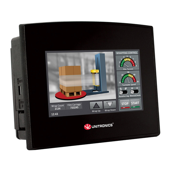
The SAMBA SM43-J-R20/SM43-J-T20 OPLC is an All-in-One Programmable Logic Controller that
Comprises a built-in 4.3" Color Touchscreen.
The SAMBA SM35-J-R20/SM35-J-T20 OPLC is an All-in-One Programmable Logic Controller that
Comprises a built-in 3.5" Color Touchscreen.
Communications
For SM43: USB device programming port (Mini-B)
For SM35: 1 build-in serial port:RS232
Optional: the user may install -
RS232/RS485 port (V100-17-RS4/V100-17-RS4X) or Ethernet (V100-17-ET2)
& CANbus (V100-17-CAN)
Standard Kit Contents
Samba controller
I/O connectors (x2)
Battery (installed)
Alert Symbols and General Restrictions
When any of the following symbols appear, read the associated information carefully.
Symbol
Meaning
Danger
Warning
Caution
Caution
Before using this product, the user must read and understand this document.
All examples and diagrams are intended to aid understanding, and do not guarantee operation.
Unitronics accepts no responsibility for actual use of this product based on these examples.
Please dispose of this product according to local and national standards and regulations.
Only qualified service personnel should open this device or carry out repairs.
Failure to comply with appropriate safety guidelines can cause severe injury or property damage.
Do not attempt to use this device with parameters that exceed permissible levels.
To avoid damaging the system, do not connect/disconnect the device when power is on.
Environmental Considerations
Do not install in areas with: excessive or conductive dust, corrosive or flammable gas,
moisture or rain, excessive heat, regular impact shocks or excessive vibration, in
accordance with the standards given in the product's technical specification sheet.
Do not place in water or let water leak onto the unit.
Do not allow debris to fall inside the unit during installation.
Ventilation: 10mm space required between controller's top/bottom edges & enclosure walls.
Install at maximum distance from high-voltage cables and power equipment.
Unitronics
8-800-511-65-88 (Бесплатно по России)
OPLC Installation Guide
12 Digital Inputs, include 1 HSC/Shaft-encoder Input,
2 Analog inputs (only when the digital inputs are set to pnp),
8 Relay Outputs
12 Digital Inputs, include 3 HSC/Shaft-encoder Input,
2 Analog inputs, 8 Transistor Outputs
Mounting brackets (x2)
Rubber seal
Description
The identified danger causes physical and property damage.
The identified danger could cause physical and property damage.
Use caution.
1
Advertisement
Table of Contents

Related Manuals for Unitronics Samba OPLC SM43-J-R20


Summary of Contents for Unitronics Samba OPLC SM43-J-R20
- Page 1 All examples and diagrams are intended to aid understanding, and do not guarantee operation. Unitronics accepts no responsibility for actual use of this product based on these examples. Please dispose of this product according to local and national standards and regulations.
- Page 2 Samba™ OPLC™ Installation Guide Mounting Dimensions SM43-J-R20/SM43-J-T20 SM35-J-R20/SM35-J-T20 Unitronics...
-
Page 3: Panel Mounting
Note For UL listed module, in order to meet the UL508 standard, panel-mount this device on the flat surface of a Type 1 enclosure. Unitronics... - Page 4 To avoid damaging the wire, do not exceed a maximum torque of 0.5 N·m (5 kgf·cm). Do not use tin, solder, or any substance on stripped wire that might cause the wire Caution strand to break. Install at maximum distance from high-voltage cables and power equipment. Unitronics...
-
Page 5: Wiring Procedure
- Inputs 1, 3, and 5 can function as either counter reset, as part of a shaft-encoder, or as normal digital inputs. - If inputs 0, 2, 4 are set as high-speed counters (without reset), inputs 1, 3, 5 can function as normal digital inputs. Unitronics... - Page 6 Set to JP1 (all Inputs) npn (sink) pnp(source)* Inputs 10/11: Set as Digital or Analog Set to JP5 (Input 10) JP6 (Input 11) Digital* Analog Analog Inputs AN0/AN1: Set Type Set to JP3 (AN0) JP4 (AN1) Voltage* Current *Default settings Unitronics...
-
Page 7: Opening The Controller
Closing the Controller 1.Replace the back cover of the controller and fasten the corner screws. Note that you must replace the back cover securely before powering up the controller. I/O Wiring npn Input Wiring SM43-J-R20/SM35-J-R20 SM43-J-T20/SM35-J-T20 Input wiring, npn (sink) Unitronics... - Page 8 Samba™ OPLC™ Installation Guide HSC input wiring, npn (sink) pnp Input Wiring SM43-J-R20/SM35-J-R20 SM43-J-T20/SM35-J-T20 Input wiring, pnp (source) HSC input wiring, pnp (source) Unitronics...
- Page 9 SM43-J-T20/SM35-J-T20 Analog Input Wiring SM43-J-R20/SM35-J-R20 SM43-J-T20/SM35-J-T20 Analog input wiring, current (2/3 wire) Analog input wiring, current/voltage (4-wire) Shields should be connected at the signal’s source. The 0V signal of the analog input must be connected to the controller’s 0V. Unitronics...
-
Page 10: Power Supply
5. Do not connect either the ‘Neutral’ or ‘Line’ signal of the 110/220VAC to device’s 0V pin. 6. In the event of voltage fluctuations or non- conformity to voltage power supply specifications, connect the device to a regulated power supply. Unitronics... -
Page 11: Communication Port
Not connected 0V reference TXD signal RXD signal 0V reference Not connected Чтобы подобрать подходящую модель, уточнить стоимость и срок поставки обращайтесь к нашим специалистам по электронной почте i@sp-t.ru или по телефонам +7(499)707-11-20 +7(499)707 11 30, 8-800-511-65-88 (Бесплатно по России) Unitronics...
Need help?
Do you have a question about the Samba OPLC SM43-J-R20 and is the answer not in the manual?
Questions and answers