Table of Contents
Advertisement
Quick Links
®
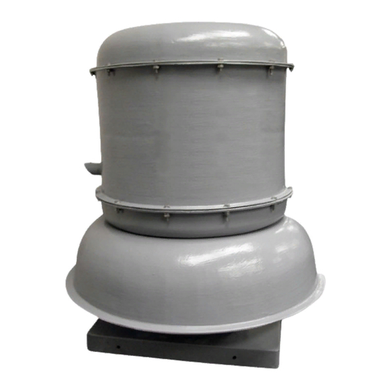
This publication contains the installation, operation and
maintenance instructions for standard units of the FCED,
FCEB, FCRUD and FCRUB Fiberglass Roof Exhausters.
Carefully read this publication and any
supplemental documents prior to any
installation or maintenance procedure.
Loren Cook catalog, Fiberglass, provides additional
information describing the equipment, fan performance,
available accessories and specification data.
For additional safety information, refer to AMCA Publi-
cation 410-96, Safety Practices for Users and Installers of
Industrial and Commercial Fans.
All of the publications listed above can be obtained from:
• lorencook.com
• info@lorencook.com
• 417-869-6474 ext. 166
For information and instructions on special equipment,
contact Loren Cook Company at 417-869-6474.
Receiving and Inspection
Carefully inspect the fan and accessories for any dam-
age and shortage immediately upon receipt of the fan.
• Turn the wheel by hand to ensure it turns freely and does not
bind.
• Check dampers (if supplied) for free operation of all moving
parts.
• Record on the Delivery Receipt any visible sign of damage.
Handling
Lift the fan by the base.
NOTICE! Never lift by the shaft, motor or housing.
Storage
If the fan is stored for any length of time prior to installa-
tion, completely fill the bearings with grease or moisture-
inhibiting oil (refer to Lubricants, page 6). Rotate the wheel
several revolutions every three to five days to keep a coat-
ing of grease on all internal bearing parts.
Store the fan in its original crate and protect it from dust,
debris and weather.
FCE
FCE/FCRU IO&M
INSTALLATION, OPERATION AND MAINTENANCE MANUAL
FCRU
1
FCE/FCRU
Fiberglass Roof Exhausters
Rotating Parts & Electrical Shock Hazard:
Fans should be installed and serviced by qualified person-
nel only.
Disconnect electric power before working on unit (prior to
removal of guards or entry into access doors).
Follow proper lockout/tagout procedures to ensure the unit
cannot be energized while being installed or serviced.
A disconnect switch should be placed near the fan in order
that the power can be swiftly cut off, in case of an emer-
gency and in order that maintenance personnel are pro-
vided complete control of the power source.
Grounding is required. All field-installed wiring must be
completed by qualified personnel. All field installed wiring
must comply with National Electric Code (NFPA 70) and all
applicable local codes.
Fans and blowers create pressure at the discharge and
vacuum at the inlet. This may cause objects to get pulled
into the unit and objects to be propelled rapidly from the
discharge. The discharge should always be directed in a
safe direction and inlets should not be left unguarded. Any
object pulled into the inlet will become a projectile capable
of causing serious injury or death.
When air is allowed to move through a non-powered fan,
the impeller can rotate, which is referred to as windmill-
ing. Windmilling will cause hazardous conditions due to
unexpected rotation of components. Impellers should be
blocked in position or air passages blocked to prevent draft
when working on fans.
Friction and power loss inside rotating components will
cause them to be a potential burn hazard. All components
should be approached with caution and/or allowed to cool
before contacting them for maintenance.
Under certain lighting conditions, rotating components
may appear stationary. Components should be verified to
be stationary in a safe manner, before they come into con-
tact with personnel, tools or clothing.
Failure to follow these instructions could result in death or
serious injury.
The attachment of roof mounted fans to the roof curb as
well as the attachment of roof curbs to the building struc-
ture must exceed the structural requirements based on the
environmental loading derived from the applicable build-
ing code for the site. The local code official may require
variations from the recognized code based on local data.
The licensed engineer of record will be responsible for pre-
scribing the correct attachment based on construction ma-
terials, code requirements and environmental effects spe-
cific to the installation.
B51150-003
Advertisement
Table of Contents

Related Manuals for COOK FCE Series


Summary of Contents for COOK FCE Series
- Page 1 Disconnect electric power before working on unit (prior to Loren Cook catalog, Fiberglass, provides additional removal of guards or entry into access doors). information describing the equipment, fan performance, available accessories and specification data.
-
Page 2: Damper Installation
To maintain good working condition of the fan when it is 1. Remove the top cap which covers the motor assembly stored outdoors, follow the additional instructions below. by unbolting the lid. • Coat the shaft with grease or a rust preventative 2. -
Page 3: Wiring Diagrams
Wiring Diagrams 3 Phase, 9 Lead Motor 3 Phase, 9 Lead Motor 3 Phase, 9 Lead Motor Single Speed, Single Phase Motor Y-Connection Delta-Connection Ground A Low Voltage High Voltage Low Voltage High Voltage 208/230 Volts 460 Volts 208/230 Volts 460 Volts 4 5 6 7 8 9... -
Page 4: Maintenance
Inspection Bearings should be relubricated in accordance with the condition chart below. Inspection of the fan should be conducted at the first 30 Conditions Chart minute, 8 hour and 24 hour intervals of satisfactory op- Temp. °F Greasing Interval eration. During the inspections, stop the fan and inspect -30 to 120 6 months as per the chart below. -
Page 5: Pulley Alignment
Should the motor prove defective within a one-year pe- Belt tension is determined by the sound of the belts when riod, contact your local Loren Cook representative or your the fan is first started. The belts will produce a loud squeal, nearest authorized electric motor service representative. -
Page 6: Bearing Replacement
Bearing Replacement Wheel-to-Inlet Clearance The fan bearings are pillow block ball bearings. The correct wheel-to-inlet clearance is critical to proper 1. Follow all local lock-out/tag-out procedures, remove fan performance. This clearance should be verified before topcap from unit and unwire the units motor. initial start-up since rough handling during shipment could 2. -
Page 7: Troubleshooting
Troubleshooting Problem and Potential Cause Low Capacity or Pressure: • Incorrect direction of rotation. Make sure the fan rotates in same direction as the arrows on the motor or belt drive assembly. • Poor fan inlet conditions. There should be a straight clear duct at the inlet. -
Page 8: Limited Warranty
Cook Company, General Offices, 2015 East Dale Street, Springfield, Missouri 65803-4637, explaining in writing, in detail, your complaint and referring to the specific model and serial numbers of your fan. Upon receipt by Loren Cook Company of your written complaint, you will be notified, within thirty (30) days of our receipt of your complaint, in writing, as to the manner in which your claim will be handled.
Need help?
Do you have a question about the FCE Series and is the answer not in the manual?
Questions and answers