Table of Contents
Advertisement
Quick Links
Advertisement
Table of Contents

Related Manuals for IKA RC 5 basic


Summary of Contents for IKA RC 5 basic
- Page 1 IKA RC 5 basic Operating instructions...
-
Page 2: Device Setup
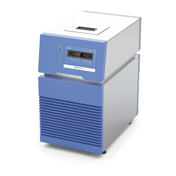
Device setup Fig. 1 Item Designation Filling opening lid Operator panel and display Handle Venting grid RS 232 port USB port Pump connector IN Pump connector OUT Power switch Power socket Backflow Overflow... -
Page 3: Table Of Contents
Preparations ..............................7 Setting up �������������������������������������������������������������������������������������������������������������������������������������������������������������7 Connecting the tubings �����������������������������������������������������������������������������������������������������������������������������������������7 Filling and draining ������������������������������������������������������������������������������������������������������������������������������������������������8 Fluid (Standard information for IKA fluid) ������������������������������������������������������������������������������������������������������������10 Moving the device ����������������������������������������������������������������������������������������������������������������������������������������������11 Operator panel and display ........................11 Commissioning and operating ........................12 Menu settings ............................13 Menu structure ���������������������������������������������������������������������������������������������������������������������������������������������������13... -
Page 4: Eu Declaration Of Conformity
2004/108/EC and 2011/65/EU and conforms with the standards or other normative documents: EN 61010-1, EN 61010-2-010, EN 61326-1, EN 60529, EN ISO 12100 and DIN 12876-1� A copy of the complete EU Declaration of Conformity can be requested at sales@ika�com� Explication of warning symbols... -
Page 5: Safety Instructions
For ex- tional or local regulations ample, users can implement comprehensive monitoring equipment� • Process pathogenic material only in closed vessels under a suitable fume hood� Please contact IKA application sup- port if you have any question�... -
Page 6: Fluids
Fluids: Refrigerant: Only use the fluids, which fulfill the The device is not allowed to be WARNING WARNING requirements for safety, health and used in an ATEX (Atmosphere EX- device compatibility� Be aware of losible) zone� the chemical hazards that may be associated with the bath fluid used�... -
Page 7: Intended Use
The safety of the user cannot be guaranteed: culating fluids� - If the device is operated with accessories that are not sup- plied or recommended by IKA� Intended Use: Tabletop device - If the device is operated improperly or in contrary to the IKA specifications�... -
Page 8: Filling And Draining
- Connect the power plug and turn on the device with When IKA calorimeter is not connected, please close the power switch� “Backflow” connector with included backflow cap� - The low level warning message appear on the display�... - Page 9 Note: Pay attention to the fluid level information: Low Level High Level Red (High Level) Red (Low Level) Fig. 7 - To drain the fluid from the bath, connect a hose to the drain port and turn the drain valve in counter clockwise direction with a straight screwdriver�...
-
Page 10: Fluid (Standard Information For Ika Fluid)
Fluids (Standard information for IKA fluid): Operating temperature Operating temperature Safety temperature Flash point Designation range for open bath range for closed bath (°C) (°C) application applications (°C) (°C) CF�EG28�N10�80�8 -10 ��� 80 -10 … 80 CF�EG39�N20�80�16 -20 … 80 -20 …... -
Page 11: Moving The Device
Moving the device: Empty all fluid in the bath before moving device from one place to other place� The device must be lifted by two persons with the upper handles� It can also be moved on flat surface by lifting and pushing the front of the device�... -
Page 12: Commissioning And Operating
Commissioning and operation Note: Before commissioning, make sure that the device has Then the device enters standby status and is ready for op- not been moved for one hour� eration� Check whether the voltage specified on the type plate Change the temperature setting with “Temp (+)“ button matches the power voltage available�... -
Page 13: Menu Settings
Maximum temperature (HIT): The chosen fluid (No�) limits the maximum and minimum temperature� Customized fluid (No�: 8) enables the whole working temperature range� See Section “Fluids (Standard information for IKA fluid)”� The maximum adjustable value: 40 °C�... -
Page 14: Temperature Control Type (Auto)
Temperature control type (AUTO): Proportional coefficient of PID (Kp 1): AUTO 1: AUTO 1 is the default setting� The default PID The proportional coefficient Kp is the controller amplifica- settings are used automatically� tion and determines how strongly the control deviation (the Cooling down curve in auto-turning control (AUTO 1): difference between the target temperature and actual tem- perature) directly affects the control variable (cooling down... -
Page 15: Reset To Factory Settings (Rst)
Example: 2-point calibration: Input the calibration value from the reference measuring Dip the temperature sensor of the reference measuring in- instrument (e�g� 10�1 °C) with “Pump (+)” button (I) or strument into the bath fluid� “Pump (-)” button (J)� Select 2-point calibration in the menu� Press the “OK/ Pump“... -
Page 16: Interface And Output
1�1)� The NAMUR commands and the additional specific IKA co mmands serve only as low level commands for communica- tion between the device and the PC� With a suitable terminal or communications programme these commands can be transmitted directly to the circulator equipment�... - Page 17 Commands: NAMUR Commands Function IN_PV_2 Read the internal actual temperature IN_PV_4 Read the pump actual speed IN_SP_1 Read the internal setting temperature IN_SP_4 Read the pump setting speed OUT_SP_1 xxx Set the internal setting temperature XXX OUT_SP_12@n Set the WD safety temperature with echo of the set (defined) value� OUT_SP_4 xxx Set the pump speed XXX OUT_SP_42@n...
-
Page 18: Maintenance And Cleaning
The protective media stops the - manufacturing number, see type plate growth of algae, bacteria and other microorganisms� - item and designation of the spare parts, see www.ika.com - software version� To keep the full cooling performance, the dust filter of the cooler must be checked regularly and cleaned if necessary�... -
Page 19: Error Codes
Silicone tube (nominal width 12 mm) Labworldsoft ® H.PUR.8 PUR tube (nominal width 8 mm) H.PUR.12 PUR tube (nominal width 12 mm) H.FKM.8 FKM tube (nominal width 8 mm) H.FKM.12 FKM tube (nominal width 12 mm) See more accessories on www.ika.com�... -
Page 20: Technical Data
Technical data Operating voltage 230 ± 10 % 100 ��� 115 ± 10 % Frequency 50 / 60 Max� input power 1100 Working temperature range °C - 30 ��� RT Operating temperature range (with external heating) °C - 30 ��� + 80 Temperature stability –... -
Page 21: Warranty
Warranty In accordance with IKA warranty conditions, the warranty The warranty does not cover worn out parts, nor does it ap- period is 24 months� For claims under the warranty please ply to faults resulting from improper use, insufficient care or contact your local dealer�... - Page 22 VIETNAM IKA Vietnam Company Limited Phone: +84 28 38202142 eMail: sales�lab-vietnam@ika�com Discover and order the fascinating products of IKA online: www.ika.com IKAworldwide IKAworldwide /// #lookattheblue @IKAworldwide Technical specifications may be changed without prior notice�...
Need help?
Do you have a question about the RC 5 basic and is the answer not in the manual?
Questions and answers