Table of Contents
Advertisement
Advertisement
Table of Contents

Related Manuals for IKA Plate RCT digital


Summary of Contents for IKA Plate RCT digital
- Page 1 IKA Plate (RCT digital) RCT 5 digital...
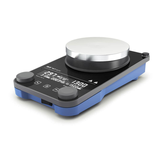
- Page 2 Fig. 1...
-
Page 3: Table Of Contents
EU Declaration of conformity �������������������������������������������������������������6 Explication of warning symbols ��������������������������������������������������������� 6 Safety instructions ����������������������������������������������������������������������������� 7 Intended use ����������������������������������������������������������������������������������� 10 Unpacking �������������������������������������������������������������������������������������� 11 Installation �������������������������������������������������������������������������������������� 12 Operator panel and display ������������������������������������������������������������� 15 Operation ��������������������������������������������������������������������������������������� 17 Interfaces and outputs �������������������������������������������������������������������� 29 Maintenance and cleaning �������������������������������������������������������������� 32 Accessories �������������������������������������������������������������������������������������... -
Page 4: Eu Declaration Of Conformity
2006/42/EC, 2014/30/EU and 2011/65/EU and conforms with the following standards or nor- mative documents: EN 61010-1, EN 61010-2-010, EN 61010-2-051, EN 61326-1, EN 60529 and EN ISO 12100� A copy of the complete EU Declaration of Conformity can be requested at sales@ika�com� Explication of warning symbols /// Warning symbols... -
Page 5: Safety Instructions
Safety instructions /// General information › Read the operating instructions in its entirety before using the device and follow the safety instructions. › Keep the operating instructions in a place where it can be accessed by everyone� › Ensure that only trained staff work with the device� ›... - Page 6 - an error message is displayed� /// Accessories › Safe operation is guaranteed only with the use of original IKA accessories� › Ensure that the external temperature sensor is inserted into the medium to a depth of at least 20 mm when connected�...
- Page 7 /// For protection of the equipment › The device may only be opened by qualified and IKA approved experts� › Do not cover the device, even partially e�g� with metallic plates or film� This may result in overheating�...
-
Page 8: Intended Use
Intended use /// Use › The magnetic stirrer is suitable for mixing and / or heating substances� /// Area of use › Indoor environments similar to that a laboratory of research, teaching, trade or industry area� › The safety of the user cannot be guaranteed: - if the device is operated with accessories that are not supplied or recommended by the manufacturer, - if the device is operated improperly or contrary to the manufacture’s specifications,... -
Page 9: Unpacking
Unpack the device carefully� Any damage should immediately be reported to the carrier (mail, rail or freight forwarding company)� /// Scope of delivery IKA Plate (RCT digital) RCT 5 digital IKA Plate (RCT digital) / RCT 5 digital Power cord USB cord Temperature sensor PT 1000�60 Screwdriver (safety circuit) -
Page 10: Installation
Installation /// Assembling support rod / extension etc� › Review the mounting and safety instructions of the IKA boss head clamp prior to using it� (see “Accessories”) › The device must not be suspended from the support rod! Risk of tipping! ›... - Page 11 ≤ 90 mm /// Connecting an external temperature sensor / thermometer 1� Switch off the device [main switch (A)]� 2� Connect safety contact thermometers according to DIN 12878 Class 2 or Temperature sensor PT 1000 (single sensor) to the connection (M)� 3�...
-
Page 13: Operator Panel And Display
Operator panel and display /// Operator panel Main switch (left « on, right « off) Standby LED Adjustable safety circuit Power socket Rotating / pressing knob - Temperature USB Interface setting RS 232 Interface Rotating / pressing knob - Speed setting Connection for PT 1000 temperature “Menu“... - Page 14 /// Display 14 | 13 09 11 10 15 17 16 SAFE VISC Set speed value Operating mode Set temperature value Safety circuit temperature Motor running / rotation direction Viscosity trend value Timer / counter 13 | PT 1000 temperature sensor connected ETS-D5 / ETS-D6 connected Temperature unit All parameters locked...
-
Page 15: Operation
Operation /// Start-up (°C / °F) (rpm) SAFE Temp 0...310 °C Speed 0...1500 rpm... - Page 16 /// Stirring › Set the speed using the rotating / pressing knob (D)� The set speed value is shown on the right of the display� › Press the rotating / pressing knob (D) to start the stirring function� (rpm) 0...1500 rpm SAFE Temp 0...310 °C Speed 0...1500 rpm...
- Page 17 /// Heating Setting the safety temperature limit: The maximum achievable heating plate temperature is restricted by an adjustable safety tem- perature limit� Once this limit has been reached, the device stops heating� Notice! The denominated temperatures should always refer to the center of the heating plate� Warning! The safety temperature limit must always be set at least 25 °C lower than the flash point of the media to be processed!
- Page 18 (°C / °F) 0...310 °C ≤ Safe temp. − 15 °C SAFE PID / 2P / PI Temp 0...310 °C Speed 0...1500 rpm SAFE Temp 0...310 °C Speed 0...1500 rpm SAFE SAFE Temp 0...310 °C Speed 0...1500 rpm Temp 0...310 °C Speed 0...1500 rpm SAFE Temp 0...310 °C...
- Page 19 › The set and actual temperature values are shown permanently on the display� › When the heating function is switched on, the “Heating function activated” symbol displayed� › When the device is switched off while the heating plate temperature is higher than 50 °C, the display shows “Hot!”...
- Page 20 /// Menu structure Factory settings Operating mode Temperature control mode Intermittent mode / Intermittent mode Run time 00:00 [mm:ss] Rotation direction Pause time 00:03 [mm:ss] Rotation direction Clockwise (continuous) Automatic reverse rotation Beep Temperature unit °C ...
- Page 21 /// Menu details Operating mode: Mode A: All settings will be stored if the device is switched off or disconnected from the power supply� The stirring and heating functions will be set to OFF when the device is powered on� The safety circuit can be set or modified�...
- Page 22 Intermittent mode / Rotation direction: Intermittent mode: In intermitted mode, the stirring function is interrupted cyclically� The run time (0 / 10 sec – 10 min, 10 sec steps) and pause time (3 sec – 5 min, 1 sec steps) should both be set� When the intermittent mode is activated, a decimal point appears on the display ( )�...
- Page 23 Safe / Visc: Once the “VISC / SAFE“ has been set to “VISC“, the viscosity trend value will be shown on the display� The torque trend measurement is used to deduce the change in viscosity of the reaction medium� The devices are not designed to measure absolute viscosity� They only measure and display the relative change in the viscosity of the medium from a starting point specified by the user�...
- Page 24 Probe cal. “EXT” temp. 1st speed 1st temp. SAFE SAFE SAFE SAFE SAFE = 1st temp. = 2nd temp. 2nd temp. “EXT“ temp. SAFE Software version: Turn the rotating / pressing knob (D) to change the menu item to ”Software version”� /// Timer / Counter ›...
- Page 26 Timer mode (count down): › Set the desired value with the rotating / pressing knob (D)� By pressing the knob the value is confirmed� › Pressing the button (F) to start the timer� › To pause the timer, press the button (F)� ›...
-
Page 27: Interfaces And Outputs
First, download the latest driver for IKA devices with USB interface from: http://www.ika.com/ika/lws/download/usb-driver.zip Install the driver by running the setup file� Then connect the IKA device to the PC via the USB data cable and follow the instructions� The data communication is via a virtual COM port�... - Page 28 1�1)� The NAMUR commands and the additional specific IKA commands commissioning serve only as low level commands for communication between the device and the PC� With a suitable ter- minal or communications program these commands can be transmitted directly to the device�...
- Page 29 ”Watchdog” functions, monitoring of the serial data flow: If, once this function has been activated (see NAMUR commands), there is no retransmission of the command from the computer within the set time (“watchdog time”), the heating and stirring functions are switched off in accordance with the set “watchdog” function or are changed to the set target values�...
-
Page 30: Maintenance And Cleaning
/// Cleaning: › For cleaning disconnect the mains plug! › Use only cleaning agents which have been approved by IKA to clean IKA devices� These are water (with tenside) and isopropanol� › Wear protective gloves during cleaning the devices�... -
Page 31: Error Codes
Error codes › The fault is shown by an error code on the display as following if the error occurs� Proceed as follows in such cases: - Turn off the device by using the main switch (left « on, right « off)� - Carry out corrective measures�... - Page 32 Er06 - Interruption of the safety circuit Causes › break in safety circuit Effect › heating switched off Solutions › plug in contact plug › plug in PT 1000 temperature sensor › replace faulty connecting cable, plug, or contact thermometer Er13 - Hotplate safety sensor, open-circuit Causes ›...
- Page 33 Er26 – Plate temperature > plate safety temperature (more than 40 K) Causes › irregular temperature distribution across heating plate due to sporadic heat dissipation › defective control or safety temperature sensor Effect › heating switched off Solutions › switch device off, leave to cool and switch on again ›...
-
Page 34: Technical Data
Technical data IKA Plate (RCT digital) RCT 5 digital General data Voltage 220 – 230 VAC ± 10 % 115 VAC ± 10 % 100 VAC ± 10 % Frequency 50 / 60 Hz Power input 650 W 900 W Power input standby 1�6 W... - Page 35 Heating function Heat output 600 W 850 W Heating temperature range RT + device self-heating ��� 310 °C Temperature setting range 0 ��� 310 °C Temperature display set-value Temperature display actual-value Temperature setting rotating / pressing knob Temperature setting resolution of heating plate Temperature setting resolution of medium Heating rate (1 l water in H 1500) 6�5 K / min...
-
Page 36: Warranty
Warranty › In accordance with IKA warranty conditions, the warranty period is 24 months� For claims under the warranty please contact your local dealer� You may also send the device direct to our factory, enclosing the delivery invoice and giving reasons for the claim� You will be liable for freight costs�...
Need help?
Do you have a question about the Plate RCT digital and is the answer not in the manual?
Questions and answers