Table of Contents
Advertisement
Quick Links
Please note that Cypress is an Infineon Technologies Company.
The document following this cover page is marked as "Cypress" document as this is the
company that originally developed the product. Please note that Infineon will continue
to offer the product to new and existing customers as part of the Infineon product
portfolio.
Continuity of document content
The fact that Infineon offers the following product as part of the Infineon product
portfolio does not lead to any changes to this document. Future revisions will occur
when appropriate, and any changes will be set out on the document history page.
Continuity of ordering part numbers
Infineon continues to support existing part numbers. Please continue to use the
ordering part numbers listed in the datasheet for ordering.
www.infineon.com
Advertisement
Table of Contents
Troubleshooting

Related Manuals for Infineon Cypress CYW954907AEVAL1F


Summary of Contents for Infineon Cypress CYW954907AEVAL1F
- Page 1 The document following this cover page is marked as “Cypress” document as this is the company that originally developed the product. Please note that Infineon will continue to offer the product to new and existing customers as part of the Infineon product portfolio.
- Page 2 CYW954907AEVAL1F Evaluation Kit User Guide Document Number: 002-22338 Rev. *A Cypress Semiconductor An Infineon Technologies Company 198 Champion Court San Jose, CA 95134-1709 www.cypress.com www.infineon.com...
- Page 3 Copyrights Copyrights © Cypress Semiconductor Corporation, 2018-2020. This document is the property of Cypress Semiconductor Corporation and its subsidiaries ("Cypress"). This document, including any software or firmware included or referenced in this document ("Software"), is owned by Cypress under the intellectual property laws and treaties of the United States and other countries worldwide.
-
Page 4: Table Of Contents
Contents Safety Information 1. Introduction CYW954907AEVAL1F EVK Contents .................6 Board Details .......................8 WICED Studio Development System Overview ............10 WICED Studio Code Examples .................11 Kit Code Examples ....................12 Getting Started......................12 IoT Resources and Technical Support ..............13 Additional Learning Resources..................13 Document Conventions .....................13 1.10 Acronyms........................14 2. - Page 5 Contents User Switches......................33 LED..........................34 Reset Control......................34 Ethernet ........................35 Micro SD Connector/Slot ...................37 JTAG Connector ......................37 4.7.1 On-board Programmer/Debugger and Serial Interface Chip......37 4.7.2 External JTAG ....................38 Connectors ........................39 4.8.1 WICED Header ....................39 4.8.2 Arduino-Compatible Headers.................40 UART Port Configuration on CYW954907AEVAL1F Kit..........42 4.10 External ADC ......................42 4.11 PWM ..........................43 5.
-
Page 6: Safety Information
Safety Information The CYW954907AEVAL1F EVK is intended for use as a development platform for hardware or soft- ware in a laboratory environment. The board is an open-system design, which does not include a shielded enclosure. Due to this reason, the board may cause interference with other electrical or electronic devices in close proximity. -
Page 7: Introduction
Introduction Thank you for your interest in the CYW954907AEVAL1F Evaluation Kit (EVK). The EVK enables customers to evaluate and develop single-chip Wi-Fi applications using CYW54907 devices. The EVK uses WICED Studio 6.0 (or later) to develop and debug your CYW54907 project. It offers footprint-compatibility with Arduino shields. - Page 8 Introduction Figure 1-1. CYW954907AEVAL1F Kit Contents Inspect the contents of the kit. If you find any part missing, contact your nearest Cypress sales office for assistance: www.cypress.com/support. Hardware Not Included with the Kit The EVK does not come with all the hardware needed to perform the demonstrations documented in this guide.
-
Page 9: Board Details
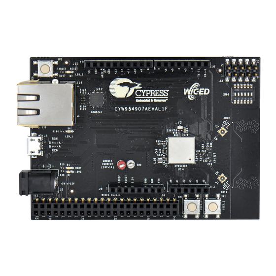
Introduction Board Details The board consists of the blocks shown in Figure 1-2 Figure 1-3. 1. Reset Switch (SW2) 2. RJ45 Connector (J14) 3. Micro USB (Programming and Debugging) (J5) 4. 5-12V Power Input (J8) 5. WICED Header (J6) 6. Arduino Header (J13) 7. - Page 10 Introduction Figure 1-3. CYW954907AEVAL1F Evaluation Board (Back View) CYW954907AEVAL1F Evaluation Kit User Guide, Document Number: 002-22338 Rev. *A...
-
Page 11: Wiced Studio Development System Overview
Introduction WICED Studio Development System Overview WICED Studio 6.0 (or later) supports application development using the WICED Evaluation Board (CYW954907AEVAL1F EVK). Tabs and their location in the WICED IDE are as shown in Figure 1-4. Figure 1-4 illustrates the following: 1. -
Page 12: Wiced Studio Code Examples
Introduction WICED Studio Code Examples WICED Studio includes libraries and code examples supporting both Bluetooth and Wi-Fi platforms. Selecting the 43xxx_Wi-Fi Filter will show only Wi-Fi platform related files in the project explorer as shown in Figure 1-5. Application examples can speed up the design process by serving as templates for development. Code examples are located under the apps category (in the Project explorer window), as shown in Figure 1-6. -
Page 13: Kit Code Examples
Introduction Figure 1-6. Code Examples under apps Category Kit Code Examples In addition to the examples available in WICED Studio, this EVK includes a few additional code examples, which can be used to quickly evaluate CYW54907 using this kit. These examples are described in the Code Examples chapter. -
Page 14: Iot Resources And Technical Support
Introduction IoT Resources and Technical Support Cypress provides a wealth of data at www.cypress.com/internet-things-iot to help you to select the right IoT device for your design, and quickly and effectively integrate the device into your design. Cypress provides customer access to a wide range of information, including technical documentation, schematic diagrams, product bill of materials, PCB layout information, and software updates. -
Page 15: Acronyms
Introduction 1.10 Acronyms Table 1-2. List of Acronyms used in this Document Acronym Definition Serial Peripheral Interface Evaluation Kit Software Development Kit WICED Wireless Internet Connectivity for Embedded Devices JTAG Joint Test Action Group Inter-Integrated Circuit MQTT Message Queue Telemetry Transport Power-on-Reset Power Management Unit VTRIM... -
Page 16: Software Installation
Software Installation This chapter describes the steps to install the software tools and packages on a PC for using the CYW954907AEVAL1F EVK. This includes the WICED IDE in which the projects will be built and used for programming. Before You Begin All Cypress software installations require administrator privileges. - Page 17 Software Installation 4. Download the CY954907AEVAL1F_KitPackage.zip software from here. The software is available as a zip file. 5. Locate the WICED Wi-Fi-SDK directory in your PC. The default location is C:\Users\<user name>\Documents\WICED-Studio-6.0\43xxx_Wi-Fi, as shown in Figure 2-1. However, it may be in a different location depending on the path you choose when installing WICED Studio.
- Page 18 Software Installation Figure 2-2. Setup Package in WICED Studio 6.0 (or later) 7. The CY954907AEVAL1F_KitPackage.zip package contains three code examples which add to the existing set of examples available in WICED Studio 6.0 or later. Unzipping creates the kits directory under apps, and adc_measure in the resources\apps directory. After unzipping, if the projects are not visible in WICED Studio 6.0 (or later), then right-click the top most folder (43xxx_Wi-Fi) and click Refresh, as shown in Figure...
-
Page 19: Kit Operation
Kit Operation This chapter introduces you to the CYW954907AEVAL1F EVK and the features that will be used as part of the kit operation. Features such as Wi-Fi connection and programming/debugging are discussed in this chapter. The chapter also describes the USB-UART that can be used to communicate with the CYW54907 device on this EVK. -
Page 20: Cyw954907Aeval1F Kit Connection
Kit Operation CYW954907AEVAL1F Kit Connection The CYW954907AEVAL1F EVK can be powered by the following options: External power supply and USB. When using an external power supply, use a 5 V - 12 V, 2A power supply with 2.1-mm DC Jack (center pin positive). -
Page 21: Troubleshooting
Kit Operation The Device Manager window identifies the WICED USB Serial COM port as COMXX. The assigned port number varies between systems. If the device displays two WICED USB Serial Ports (WICED USB Serial port and WICED USB JTAG Port) instead of one, then follow the link mentioned in this post. -
Page 22: Building, Programming, And Debugging
Kit Operation Building, Programming, and Debugging 3.4.1 Building and Programming a Project in WICED Studio IDE Do the following to build and program a project for CYW954907AEVAL1F EVK: 1. Open the WICED IDE on Windows PC: go to Start > All Programs > Cypress > WICED- Studio. - Page 23 Kit Operation 4. Enter snip.scan-CYW954907AEVAL1F download run in the Target name field and click Note: The list of all commands that can be provided in the Make target is listed in <WICED-SDK installation directory>/ 43xxx_Wi-Fi/Makefile. snip.scan-CYW954907AEVAL1F download run indicates the following: snip = directory inside apps folder scan = Sub-directory and name of the application to be built.
- Page 24 Kit Operation b. You will see the following window. Click on Serial and select corresponding COM Port for your WICED device. Then click on OK c. In the Terminal Emulator, go to Setup > Serial port…. Select the correct COM port and baud rate as follows.
-
Page 25: Troubleshooting
Kit Operation 8. The output of the Terminal Emulation program should be similar to what is shown in Figure 3-6. Figure 3-6. Console Output 3.4.2 Troubleshooting If a “download_dct” error message is displayed despite connecting the board, follow the steps outlined in this post. - Page 26 Kit Operation If -debug is not added, it will be built for release. The important difference between the debug and release configurations is the optimization. Debug is built with no optimization and release is built with optimization. It is possible to debug without using debug as well, but with many variables and lines optimized away, many breakpoints might not get hit.
- Page 27 Kit Operation 3. Open the scan.c file from the Project Explorer window. Click on the line with WPRINT_APP_INFO( ( "Waiting for scan results...\n" ) ); and press Ctrl+Shift+B. A blue hollow circle along with a check mark appears next to the line number as shown in Figure 3-8.
- Page 28 Kit Operation 8. Right-click the desired breakpoint checkbox and click Breakpoint Properties…. Click the last_built.elf check box, as shown in Figure 3-10. The check mark appears before the actual breakpoint indicating its association with the current execution. Figure 3-9. Show Breakpoints Icon Figure 3-10.
-
Page 29: Hardware
Hardware This chapter describes the CYW954907AEVAL1F EVK hardware and its different blocks, such as Bootstrap, reset control, Arduino-compatible headers, and module connectors. The schematic is available at the following location after installing the software from Software Installation: <WICED_SDK_Directory>\43xx_Wifi\platforms\CYW954907AEVAL1F\schematics Bootstrap and Control Pins Bootstrap options available in the CYW954907AEVAL1F EVK are shown in Table 4-1. - Page 30 Hardware Table 4-1. Bootstrap Options Available in CYW954907AEVAL1F EVK (continued) Strap Pull Strp Function Chip default Board Default SDIO Mode: GPIO_13 0 = SDIO Device R141=10K to WLAN_VDDIO 1 = SDIO Host Host DAP Clock Sel 1 = Enable XTAL clock for DAP sub system RF_SW_CTRL_5 0 = Disable Use Test clock TCK for DAP sub sys- PMU resource initialization mode selection...
- Page 31 Hardware 2. HIB_REG_ON_IN Used by the Hibernation (HIB) block to power up internal CYW54907 regulators. If the HIB_REG_ON_IN pin is LOW, regulators are disabled. For the HIB_REG_ON_IN pin to work as designed, HIB_REG_ON_OUT must be connected to REG_ON. The CYW54907/BCM54907 datasheet states that HIB_REG_ON_IN needs to be delayed by at least two cycles of the 32.768-kHz clock after VBAT and VDDIO have reached 90% of their final values.
- Page 32 Hardware 3. HIB_WAKE Used to wakeup chip from Hibernation mode. This pin should be pulled HIGH. Figure 4-4. HIB_WAKE Strapping Option 4. USB2_HOST_DEV_SEL Used to select the USB mode; it is set in USB DEVICE mode by default. 0 = USB HOST mode 1 = USB DEVICE mode Figure 4-5.
- Page 33 Hardware Note: Default setup is JTAG_SEL = HIGH / TAP_SEL = HIGH. Figure 4-6. JTAG_SEL and GPIO_8_TAP_SEL Strapping Option 6. GPIO_1_GSPI_MODE GPIO_1 is used for gSPI mode. By default, CYW54907 enables gSPI. 0 = gSPI engine enabled 1 = gSPI engine disabled 7.
-
Page 34: User Switches
Hardware 10. GPIO_13_SDIO_MODE GPIO_13 is used to select the SDIO mode; it is set in SDIO HOST mode by default. 0 = SDIO Device 1 = SDIO Host Figure 4-8. GPIO_13_SDIO_MODE Strapping Option 11. RF_SW_CTRL_7_RSRC_INIT_MODE_UART1_TX_OUT This pin should be pulled HIGH. Highly Recommended to pull up RF_SW_CTRL_7 via a 10K resistor to WLAN_VDDIO during bootup. -
Page 35: Led
Hardware Figure 4-9. User Switch Circuit Diagram There are two user LEDs available named LED_1 and LED_2. Table 4-3 shows the pin name and enumeration used in WICED for these LEDs. Table 4-3. User LED Available on the Board Alternate Enumeration in Switch CYW54907 Pin Name WICED_ENUM_ID... -
Page 36: Ethernet
Hardware Figure 4-11. Reset Circuit Diagram Figure 4-12. HIB_REG_ON_IN RC Delay Circuit Ethernet The Ethernet MAC Controller in the CYW54907 interfaces to an external PHY chip BCM5241 using the Media Independent Interface (MII) as shown in Figure 4-13. The same signals are also listed in Table 4-4. - Page 37 Hardware Table 4-4. CYW54907 EMAC to PHY Chip Connection (continued) SL. NO CYW54907 Pin Name Net Name in Schematic BCM5241 Pin Name RMII_G_RXD1 MII_RXD1 RXD1/ANEN_L RMII_G_RXD2 MII_RXD2 RXD2/F100 RMII_G_RXD3 MII_RXD3 RXD3/ISOLATE RMII_MDIO MII_MDIO MDIO RMII_MDC MII_MDC RMII_G_TXEN MII_TXEN TXEN RMII_G_RXDV MII_RXDV_CRS_DV RXDV PWM_2...
-
Page 38: Micro Sd Connector/Slot
Hardware Micro SD Connector/Slot Micro SD connector is connected to the SDIO Interface of CYW54907. CYW54907 supports both SDIO 3.0 Host and device modes. Figure 4-14 shows the interface between Micro SD connector and CYW54907. These signals are listed in Table 4-5. -
Page 39: External Jtag
Hardware 4.7.2 External JTAG To use the External JTAG connector (J3), set all positions in switch SW4 to closed and connect your external JTAG debugger. Ensure that the drivers for the debugger hardware are installed in the same PC where WICED Studio is installed. When using Olimex connectors, for example Olimex_ARM-USB-TINY-H, add "JTAG=Olimex_ARM-USB-TINY- H"... -
Page 40: Connectors
Hardware Connectors 4.8.1 WICED Header J6 is the WICED header available on CYW954907AEVAL1F EVK. This is a 44-pin header containing I2C, SDIO, UART, SPI, PWM lines, and I/Os. Note that some signals are shared with Arduino header (UART0 Tx/Rx) and On-board Programmer/debugger chip (UART1). Table 4-7 illustrates the J6 pinout. -
Page 41: Arduino-Compatible Headers
Hardware Table 4-7. WICED Header Pinout (continued) Eval Board CYW54907 Pin Name WICED Enumeration Alternate Enumeration Header J6.33 SDIO_CMD WICED_GPIO_43 J6.34 SDIO_DATA_3 WICED_GPIO_47 J6.35 SDIO_DATA_2 WICED_GPIO_46 J6.36 RF_SW_CTRL_6_UART1_RXD WICED_PERIPHERAL_PIN_1 WICED_UART_1 J6.37 UART1_TXD WICED_PERIPHERAL_PIN_2 WICED_UART_1 J6.38 RF_SW_CTRL_8_UART2_RXD WICED_PERIPHERAL_PIN_7 WICED_UART_3 J6.39 UART2_TXD WICED_PERIPHERAL_PIN_8 WICED_UART_3 J6.40... - Page 42 Hardware Table 4-8. Arduino Header Pinout (continued) Eval Board CYW54907 Pin Name/ ARDUINO Alternate WICED Enumeration Header Kit Signal Name Header Name Enumeration J12.6 GPIO_9 WICED_LED2 J12.7 J12.8 ARD_AREF AREF J12.9 I2C_1_SDA WICED_I2C_2 J12.10 I2C_1_SCL WICED_I2C_2 J13.1 ARD_AD0 J13.2 ARD_AD1 J13.3 ARD_AD2 J13.4...
-
Page 43: Uart Port Configuration On Cyw954907Aeval1F Kit
Hardware UART Port Configuration on CYW954907AEVAL1F Kit CYW54907 has three UART ports: slow UART, fast UART, and GCI UART. Slow UART and GCI UART are 2-wire interfaces, while fast UART is a 4-wire interface that can support up to a 3-Mbps baud rate. -
Page 44: Pwm
Hardware 4.11 There are six dedicated PWM outputs available on CYW54907. These PWMs can be multiplexed onto different pins. You can find their definitions in platforms/CYW954907AEVAL1F/platform.c inside WICED Studio. The PWMs can be reassigned to other pins by changing the first argument of the platform_pwm_t platform_pwm_peripherals structure in platform.c. - Page 45 Hardware Table 4-13. WICED_PWM_4 Combinations Pin MUX Selection Header Pin Header Name PIN_GPIO_15 (DEFAULT) J10.7 Arduino D6 PIN_GPIO_1 J10.1 Arduino D0 PIN_GPIO_7 J10.4 Arduino D3 PIN_GPIO_9 J12.9 Arduino SCK PIN_GPIO_11 J12.3 Arduino D10 PIN_GPIO_13 J10.3 Arduino D2 PIN_PWM_3 − − Table 4-14.
-
Page 46: Code Examples
Code Examples This chapter demonstrates the functionality of CYW54907 devices using the CYW954907AEVAL1F EVK code examples. Download and extract the zip file from the CYW954907AEVAL1F EVK web page as specified in the Software Installation section. The code examples once unzipped can be viewed in WICED Studio 6.0 (or later). -
Page 47: Verify Output
Code Examples 5.2.3 Verify Output Do the following to verify the output: 1. Create and run a make target for the gpio project using the description specified in Building and Programming a Project in WICED Studio IDE. After initialization of the platform, LEDs will keep flashing (toggling). When a user switch is pressed, the corresponding LED turns off. -
Page 48: Flowchart
Code Examples 5.3.3 Flowchart Figure 5-1 illustrates the config_join_ping flowchart. Figure 5-1. config_join_ping Flowchart System Initialized Initialize Command Console to STDIO UART Add New Commands to the Console Commands List Wait for Command from Console Execute Corresponding Function from command Table 5.3.4 Verify Output Do the following to verify the output:... - Page 49 Code Examples Figure 5-2. Initial Console Output 4. Type the command scan to find the list of available Wi-Fi access points as shown in Figure 5-3. CYW954907AEVAL1F Evaluation Kit User Guide, Document Number: 002-22338 Rev. *A...
- Page 50 Code Examples Figure 5-3. Scan Output 5. Type the command config <SSID> <password> . This command writes the given configuration in the Device Configuration Table (DCT). These values are stored in flash memory on the board. 6. Type the command print_config to validate if the SSID and password match and are appropriately written in the DCT.
- Page 51 Code Examples Figure 5-4. Join and Ping 8. To disconnect from the access point, use the disconnect command. The console component maintains a history of commands typed, which can be accessed using the Up/Down arrow keys. CYW954907AEVAL1F Evaluation Kit User Guide, Document Number: 002-22338 Rev. *A...
-
Page 52: Adc_Measure
Code Examples ADC_measure 5.4.1 Project Description This project demonstrates measuring values from the external ADC chip on the board and posting the values to a web page accessible from the WLAN network. This code example is based on existing code example (apps/demo/temp_control) available in the WICED Studio 6.0 (or later). On startup, the adc_measure code example joins the Wi-Fi Access Point specified in the wifi_config_dct.h file and starts a web page where the ADC count is reported. -
Page 53: Hardware Connections
Code Examples 5.4.2 Hardware Connections Connect a potentiometer (10 kΩ) between VCC and GND with the center terminal connected to channel 1 of the ADC (pin A1 in the Arduino header) as shown in Figure 5-5. If you do not have a potentiometer to test, you can connect a wire between VCC and ADC channel 2 (to simulate full scale) or a wire between GND and ADC channel 1 (to simulate zero scale). -
Page 54: Access Point Credentials
Code Examples 5.4.4 Access Point Credentials 1. Enter your credentials (SSID and pass phrase key) in the wifi_config_dct.h file. 2. Update the following macros: CLIENT_AP_SSID: update with your access point's SSID ❐ CLIENT_AP_PASSPHRASE: update with your access point's pass phrase key ❐... -
Page 55: Publish_Subscribe_Aws
Code Examples Figure 5-8. Webpage Publish_subscribe_aws 5.5.1 Project Description This project demonstrates publishing a message to a Thing in the Amazon Web Services (AWS) cloud and subscribing to the same messages. A Thing is a representation of a specific device or logical entity. -
Page 56: Hardware Connections
Code Examples 5.5.2 Hardware Connections No specific hardware connections are required for this project because all connections are hardwired on the CYW954907AEVAL1F EVK. 5.5.3 Flowchart Initialize WLAN Certificates and key valid? Bring up the WLAN interface and connect to MQTT Broker Error? Open the connection, subscribe to messages, and publish messages... -
Page 57: Verify Output
Code Examples 5.5.4 Verify Output 5.5.4.1 Set up an AWS Account and Create a Thing, Policy, and Certificate An AWS account allows you to view AWS account activity, view usage reports, and manage AWS Security Credentials. When you sign up for AWS, your AWS account is automatically signed up for all services in AWS, including AWS IoT. - Page 58 Code Examples 2. Each Thing is uniquely identified by its name. Assign a name in the Name field, and click Create thing. For example, “54907_aws”. Note: It is possible to exchange messages without a need to create a thing (by having a certificate with an attached policy), but it is recommended by AWS to create it.
- Page 59 Code Examples 3. In Add statement, specify the Action as iot:*. 4. Assign an Amazon Resource Name (ARN) in the Resource ARN field. To use a wild card, change the last part of Resource ARN as follows: "arn:aws:iot:us-east-1:xxxxxxxxxxxx:topic/replaceWithATopic" "arn:aws:iot:us-east-1:xxxxxxxxxxxx:* Notes: Use the region that you selected when you set up your account.
- Page 60 Code Examples Create a Certificate for a Thing 1. In the AWS IoT Console window, go to Manage > Things, and then click the created Thing (for example: 54907_aws). The created Thing window appears. 2. In the left navigation pane, click Security and then click Create certificate. Figure 5-11.
- Page 61 Code Examples 4. Click the Activate button and then click the Attach a policy button as shown in Figure 5-12. The Add authorization to certificate window appears (see Figure 5-13). Figure 5-12. Activate and Attach policy 5. Select the check box next to the policy you want to choose and then click Done. Figure 5-13.
- Page 62 Code Examples 12. In left navigation pane, choose Interact. 13. Copy the Endpoint from the HTTPS tab as shown in Figure 5-14 Figure 5-14. Endpoint. 14. Navigate to the publish_subscribe.c file to update the MQTT_BROKER_ADDRESS macro with the endpoint address copied from HTTPS tab. Remove the first string before "." in endpoint and replace it with * and copy it to the REGION macro.
- Page 63 Code Examples 5.5.4.3 Build, Program, and Verify Your Wi-Fi access point must be connected to the internet to verify the example. 1. Build and program the publish_subscribe_aws example using a similar procedure to the one provided in Building, Programming, and Debugging.
- Page 64 Code Examples You will see the message published as follows in Monitor section. CYW954907AEVAL1F Evaluation Kit User Guide, Document Number: 002-22338 Rev. *A...
- Page 65 Code Examples Figure 5-16. Messages Published CYW954907AEVAL1F Evaluation Kit User Guide, Document Number: 002-22338 Rev. *A...
-
Page 66: Revision History
Revision History Document Title: CYW954907AEVAL1F Evaluation Kit User Guide Document Number: 002-22338 Revision ECN# Issue Date Description of Change 6010685 01/02/2018 Initial release 6894645 06/08/2020 Revised and added contents in Section 4.1 Bootstrap and Control Pins CYW954907AEVAL1F Evaluation Kit User Guide, Document Number: 002-22338 Rev. *A...
Need help?
Do you have a question about the Cypress CYW954907AEVAL1F and is the answer not in the manual?
Questions and answers