Infineon CYW943907AEVAL1F Manual
Hide thumbs
Also See for CYW943907AEVAL1F:
- Quick start manual (4 pages) ,
- Quick start manual (13 pages)
Table of Contents
Advertisement
Quick Links
CYW943907AEVAL1F evaluation kit guide
About this document
Scope and purpose
This document serves as a guide for using the CYW943907AEVAL1F evaluation kit. The document explains
software installation, kit operation, hardware details of the board, and provides a list of code examples.
Intended audience
This guide is intended for all technical specialists who want to use the CYW943907AEVAL1F kit using
ModusToolbox™ software (2.4 or later) and are familiar with Wi-Fi connectivity. This board is intended to be
used in laboratory conditions.
Reference documents
This user guide should be read in conjunction with the following documents:
ModusToolbox™ software user guide
•
ModusToolbox™ software installation guide
•
AIROC™ CYW43907 data sheet
•
User Guide
www.infineon.com
Please read the Important Notice and Warnings at the end of this document
page 1 of 25
002-34339 Rev. *A
2022-10-10
Advertisement
Table of Contents

Related Manuals for Infineon CYW943907AEVAL1F


Summary of Contents for Infineon CYW943907AEVAL1F
-
Page 1: About This Document
Intended audience This guide is intended for all technical specialists who want to use the CYW943907AEVAL1F kit using ModusToolbox™ software (2.4 or later) and are familiar with Wi-Fi connectivity. This board is intended to be used in laboratory conditions. -
Page 2: Table Of Contents
CYW943907AEVAL1F evaluation kit guide Table of contents Table of contents About this document ........................1 Table of contents ..........................2 Safety and regulatory compliance information .................. 3 General safety instructions ............................3 ESD protection ................................3 Handling boards ................................3 Introduction .......................... -
Page 3: Safety And Regulatory Compliance Information
Handling boards CYW943907AEVAL1F boards are sensitive to ESD. Hold the board only by its edges. After removing the board from its box, place it on a grounded, static-free surface. Use a conductive foam pad if available. Do not slide the board over any surface. -
Page 4: Introduction
Introduction Introduction Thank you for your interest in the CYW943907AEVAL1F evaluation kit (EVK). This EVK enables you to evaluate and develop single-chip Wi-Fi applications using AIROC™ CYW43907 devices. The EVK uses ModusToolbox™ software (2.4 or later) to develop and debug your CYW43907 project. This EVK offers footprint-compatibility with Arduino shields. -
Page 5: Getting Started
CYW943907AEVAL1F evaluation kit guide Introduction Figure 1 Kit contents Inspect the contents of the kit; if you find any part missing, go to www.cypress.com/support. Getting started This guide will help you to get acquainted with this evaluation kit: Software installation chapter describes the installation of the kit software. -
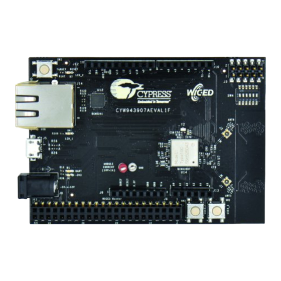
Page 6: Board Details
CYW943907AEVAL1F evaluation kit guide Introduction Board details The CYW943907AEVAL1F board consists of the blocks shown in Figure 1. Reset switch (SW2) 2. RJ45 connector (J14) 3. Micro USB (programming and debugging) (J5) 4. (Optional) 5-12 V power input (J8) 5. 44-pin expansion header with I2C, SDIO, UART, SPI, PWM lines and I/Os (J6) 6. -
Page 7: Software Development And System Overview
CYW943907AEVAL1F evaluation kit guide Introduction Software development and system overview See the ModusToolbox™ software user guide. Additional learning resources Visit CYW943907AEVAL1F EVK AIROC™ CYW43907 web pages for additional learning resources including datasheets and application notes. IoT resources and technical support Cypress provides a wealth of data at www.cypress.com/internet-things-iot... - Page 8 CYW943907AEVAL1F evaluation kit guide Introduction Abbreviation Definition Internet of Things Inter-integrated Circuit Inter-IC Sound JTAG Joint Test Action Group light-emitting diode low-power oscillator MQTT message queue telemetry transport personal computer PSoC™ programmable system-on-chip SDIO secure digital input output software development kit...
-
Page 9: Software Installation
CYW943907AEVAL1F evaluation kit guide Software installation Software installation Install software Go to the ModusToolbox™ software website ( ) and download the appropriate www.cypress.com/modustoolbox software for your platform. ModusToolbox™ software installation guide User Guide 9 of 25 002-34339 Rev. *A 2022-10-10... -
Page 10: Kit Operation
Theory of operation Figure 3 illustrates the block diagram of the CYW943907AEVAL1F evaluation board. This board contains a Type 1GC wireless module as a system-in-a-package (SiP) based on the AIROC™ CYW43907 device, which is an embedded network controller solution from Murata. This board also contains a USB-Serial interface, JTAG programmer, and a debugger. -
Page 11: Onboard Programmer/Debugger And Serial Interface Chip
CYW943907AEVAL1F evaluation kit guide Kit operation Onboard programmer/debugger and serial interface chip An FT-2232-HQ chip is used for onboard programming, debugging, and USB-serial functionality. It connects to the PC over a USB interface and connects to the AIROC™ CYW43907-based SiP module over JTAG and UART pins. - Page 12 CYW943907AEVAL1F kit selection in Project Creator tool This page lists various applications available for the CYW943907AEVAL1F kit. As you select an application, a description displays on the right. You can select multiple applications for the selected BSP by enabling the check box next to the applicable applications.
- Page 13 CYW943907AEVAL1F evaluation kit guide Kit operation When complete, the Project Creator tool closes automatically. In the IDE, a message displays about importing the project: Figure 8 Project creation process complete After several moments, the application opens with the GPIO in the project explorer, and the README.md file opens in the file viewer.
- Page 14 CYW943907AEVAL1F evaluation kit guide Kit operation Figure 10 Build the GPIO application In the Project Explorer, select the desired project. Then, in the Quick Panel, click the <app-name> Program (FTDI) link for programming the AIROC™ CYW43907 Wi-Fi connectivity processor and for debugging select <app-name>...
- Page 15 CYW943907AEVAL1F evaluation kit guide Kit operation Controls for debugging like play, step into, step return, and step over are marked in Figure Figure 12 Controls for debugging If you prefer to use the command-line option to create the project, see the README.md file of the code example.
-
Page 16: Hardware
CYW943907AEVAL1F evaluation kit guide Hardware Hardware User switches There are two user switches available on the board named USER_1 and USER_2. Table 3 shows the pin names and enumeration used in ModusToolbox™ software for the switches. Table 3 User switch AIROC™... -
Page 17: Reset Control
CYW943907AEVAL1F evaluation kit guide Hardware 4.1.2 Reset control The AIROC™ CYW43907 device can be reset using the “Target Reset” switch SW2 or a reset command from the onboard programmer/debugger and serial interface chip, as shown in Figure 14. The CYW43907 datasheet states that HIB_REG_ON_IN needs to be delayed by at least two cycles of the 32.768-kHz clock after VBAT and... -
Page 18: Connectors
Hardware Connectors Header J6 on the CYW943907AEVAL1F EVK is a 44-pin header containing I2C, SDIO, UART, SPI, PWM lines, and I/Os. Note that some signals are shared with the header compatible with Arduino (UART0 Tx/Rx) and onboard programmer/debugger chip (UART1). -
Page 19: Headers Compatible With Arduino
USB2_DP 4.2.1 Headers compatible with Arduino J9, J13, J12, and J10 are headers compatible with Arduino available in the CYW943907AEVAL1F EVK. Table 6 shows the pinout. Note the following points while connecting an Arduino shield to the board: 5-V pin of header (J9) is not connected to the board. -
Page 20: Uart Port Configuration
UART port configuration The CYW943907AEVAL1F kit has three UART ports: slow UART, fast UART, and GCI UART. Slow UART and GCI UART are 2-wire interfaces while fast UART is a 4-wire interface that can support up to a 3 Mbps baud rate. Slow UART is routed to the onboard programmer/debugger chip for UART to USB communication. -
Page 21: Pwm
CYW943907AEVAL1F evaluation kit guide Hardware There are three dedicated PWM outputs available on CYW943907AEVAL1F. Table 8 PWM header pinout Pin name on CYW43907 Header pin number Enumeration in ModusToolbox™ software J6.7 PIN_3 PIN_PWM_3 J6.1 PIN_4 PIN_PWM_4 J6.2 PIN_5 PIN_PWM_5 User Guide 21 of 25 002-34339 Rev. -
Page 22: Code Examples
CYW943907AEVAL1F evaluation kit guide Code examples Code examples The following code examples are available for the AIROC™ CYW43907 Wi-Fi connectivity processor in ModusToolbox™ software. Table 9 Code examples Code example name Description Link AIROC™ CYW43907 Hello This code example demonstrates the https://github.com/Infineon/mtb-... - Page 23 CYW943907AEVAL1F evaluation kit guide Code examples Code example name Description Link AIROC™ CYW43907 Wi-Fi This example demonstrates how to https://github.com/Infineon/mtb- scan configure different scan filters provided example-cyw43907-wifi- in the Wi-Fi Connection Manager (WCM) scan/blob/master/README.md middleware and scan for the available Wi-Fi networks.
-
Page 24: Revision History
CYW943907AEVAL1F evaluation kit guide Revision history Revision history Major changes since the last revision Date Version Description 2021-11-25 Initial release. 2022-10-10 No technical updates. Completing Sunset Review. User Guide 24 of 25 002-34339 Rev. *A 2022-10-10... - Page 25 With respect to any examples, hints or any typical WARNINGS values stated herein and/or any information 81726 Munich, Germany regarding the application of the product, Infineon Due to technical requirements products may contain Technologies hereby disclaims any and all dangerous substances. For information on the types...
Need help?
Do you have a question about the CYW943907AEVAL1F and is the answer not in the manual?
Questions and answers