Table of Contents
Advertisement
Quick Links
Advertisement
Table of Contents

Related Manuals for Razberi V8

Summary of Contents for Razberi V8
- Page 1 2020 2020 2020 2020 2020 2020 2020 2020 2020 rcgs20200916...
-
Page 2: Table Of Contents
Package Contents ........................7 V8 Overview ..........................8 Front View of Server ............................. 8 Rear View of Server ............................9 Left Control Panel View ..........................10 Right Control Panel View ..........................11 Drive Indicator Codes ..........................12 NIC Indicator Codes ............................. 13 PSU Indicator Codes ............................ - Page 3 A8 Overview ........................... 37 Front View of Server ........................... 37 Rear View of Server ............................. 37 Drive Indicator Codes ..........................38 NIC Indicator Codes ............................. 39 PSU Indicator Codes ............................ 40 LCD Panel ..............................41 System Information Label ........................... 43 M4 Overview...........................
- Page 4 Applying Enterprise iDRAC License (Purchased Separately) ..............111 Getting Help ......................... 112 Razberi Technical Support ........................112 Figure 1. Front View of V8 ..........................8 Figure 2. Rear View of V8 ..........................9 Figure 3. Left Control Panel without optional iDRAC Quick Sync 2.0 indicator .......... 10 Figure 4.
- Page 5 Figure 47. Service Tag ..........................50 Figure 48. Front and Rear Touchpoints for M4 ................... 50 Figure 49. System Dimensions for V8, V12, and V14 .................. 51 Figure 50. Dimensions for A8 ........................52 Figure 51. Dimensions for M4 ........................53 Figure 52.
- Page 6 Figure 92.iDRAC IP Settings ........................109 Figure 93. iDRAC Login ..........................110 Figure 94. Setting iDRAC Password ......................110 Table 1. Front View of V8 ..........................8 Table 2. Rear View of V8 ..........................9 Table 3. Left Control Panel View ......................... 11 Table 4.
- Page 7 Table 32. Rear View of M4 .......................... 45 Table 33. NIC Indicator Lights ........................48 Table 34. PSU Indicator ..........................49 Table 35. System Dimensions for V8, V12, and V14 ................... 51 Table 36. Dimensions for A8 ........................52 Table 37. Dimensions for M4 ........................53...
-
Page 8: Package Contents
Razberi Core Server (V8, V12, V14, A8) cartons will contain the following items. Core Server (1) • Core Server Front Bezel (1) • Rack Ready Rail Kit 1 Set (1LH & 1RH) • Power Cords (2) NEMA 5-15P to C13 Wall Plug, 125 Volt, 15 AMP, 10 Feet (3m), •... -
Page 9: V8 Overview
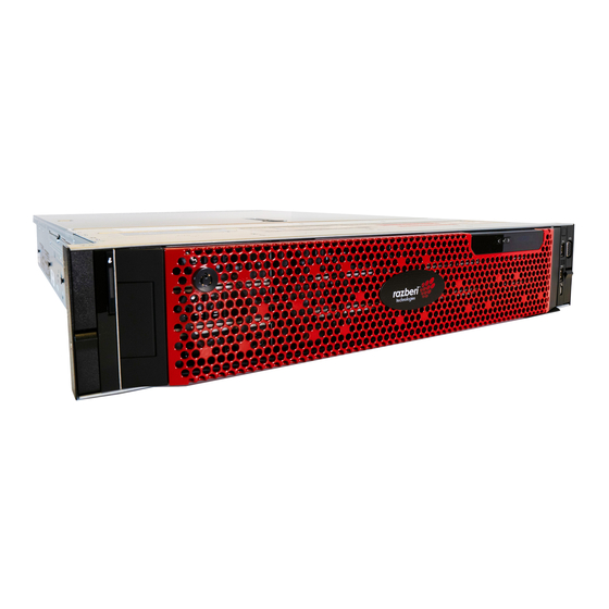
Front View of Server Figure 1. Front View of V8 Table 1. Front View of V8 Ports, Item panels, and Description slots Contains the system health and system ID, status LED, and the iDRAC Quick Sync 2 (wireless) indicator. NOTE: The iDRAC Quick Sync 2 indicator is available only on certain configurations. -
Page 10: Rear View Of Server
Rear View of Server Figure 2. Rear View of V8 Table 2. Rear View of V8 Item Features Icon Description Use the serial port to connect a serial device to the Serial port system. For more information about the supported... -
Page 11: Left Control Panel View
ID button (for more than five seconds) to enter the BIOS progress mode. Left Control Panel View Figure 3. Left Control Panel without optional iDRAC Quick Sync 2.0 indicator Figure 4. Left control panel with optional iDRAC Quick Sync 2.0 indicator V8 Overview... -
Page 12: Right Control Panel View
BIOS, and networking parameters. You can also launch the Virtual Keyboard, Video, and Mouse (KVM) viewer and virtual Kernel-based Virtual Machine (KVM), on a supported mobile device Right Control Panel View Figure 5. Right Control Panel V8 Overview... -
Page 13: Drive Indicator Codes
The activity LED indicator indicates whether the drive is currently in use or not. The status LED indicator indicates the power condition of the drive. Figure 6. Drive Indicators V8 Overview... -
Page 14: Nic Indicator Codes
The activity LED indicator indicates if data is flowing through the NIC, and the link LED indicator indicates the speed of the connected network. Figure 7. NIC Indicator Diagram NIC Indicator codes 1. link LED indicator 2. activity LED indicator V8 Overview... -
Page 15: Psu Indicator Codes
When the firmware of the PSU is being updated, the PSU handle blinks green. Blinking green CAUTION: Do not disconnect the power cord or unplug the PSU when updating firmware. If firmware update is interrupted, the PSUs do not function. V8 Overview... -
Page 16: Lcd Panel
If the LCD panel stops responding, remove the bezel and reinstall it. • If the problem persists, see Getting help. The LCD backlight remains off if LCD messaging is turned off using the iDRAC • utility, the LCD panel, or other tools. V8 Overview... -
Page 17: System Information Label
Enterprise Service Tag (EST) is found on the back of the system. Technical Support uses this information to route support calls to the appropriate personnel. Figure 10. Service Tag Diagram 1. Information Tag (front view) 2. Information Tag (back view) 3. OpenManage Mobile (OMM) label V8 Overview... - Page 18 4. iDRAC MAC address and iDRAC secure password label 5. Service Tag Figure 11. Service Information Panel with Touchpoints V8 Overview...
-
Page 19: V12 Overview
Front View of Server Figure 12. Front View of V12 Table 9. Front View of V12 Item Ports, panels, and slots Icon Description Contains the system health and system ID, status LED, and the iDRAC Quick Sync 2 (wireless) indicator. NOTE: The iDRAC Quick Sync 2 indicator is available only on certain configurations... -
Page 20: Rear View Of Server
Rear View of Server Figure 13. Rear View of V12 Table 10. Rear View of V12 Item Features Icon Description Use the serial port to connect a serial device to the system. For more Serial port information about the supported serial port, see the technical specifications section. -
Page 21: Left Control Panel View
Item Features Icon Description Status Enables you to connect the status indicator cable and view system indicator status when the CMA is installed. cable port Enables you to connect the status indicator cable and view system status when the CMA is installed. Press the system ID button: To locate a particular system within a rack. -
Page 22: Right Control Panel View
Table 11. Left Control Panel View Indicator, button, Item Icon Description or connector Status LED Indicate the status of the system. For more information, see the indicators Status LED indicators. System health and Indicates the system health. system ID indicator Indicates if the iDRAC Quick Sync 2 wireless option is activated. -
Page 23: Nic Indicator Codes
Indicator, button, or Item Icon Description connector iDRAC Direct (Micro- The iDRAC Direct (Micro-AB USB) LED indicator lights up AB USB) LED to indicate that the iDRAC Direct port is connected. Enables you to connect a display device to the VGA port system. -
Page 24: Psu Indicator Codes
PSU Indicator Codes AC power supply units (PSUs) have an illuminated translucent handle that serves as an indicator. The DC PSUs have an LED that serves as an indicator. Figure 18. PSU Indicator Diagram The indicator shows whether power is present or if a power fault has occurred. 1. -
Page 25: Lcd Panel
LCD Panel The LCD panel provides system information, status, and error messages to indicate if the system is functioning correctly or requires attention. The LCD panel can also be used to configure or view the system's iDRAC IP address. The LCD panel is available only on the optional front bezel. The optional front bezel is hot- pluggable. -
Page 26: System Information Label
Tag. Alternatively, the information may be on a sticker on the chassis of the system. The mini Enterprise Service Tag (EST) is found on the back of the system. Razberi Technologies uses this information to route support calls to the appropriate personnel. - Page 27 Figure 21. Service Information with System Touch Points V12 Overview...
-
Page 28: V14 Overview
Front View of Server Figure 22. Front View of V14 Table 16. Front View of V14 Item Ports, panels, and slots Icon Description Contains the system health and system ID, status LED, and the iDRAC Quick Sync 2 (wireless) indicator. NOTE: The iDRAC Quick Sync 2 indicator is available only on certain configurations... -
Page 29: Rear View Of Server
Item Ports, panels, and slots Icon Description The Information Tag is a slide-out label panel that contains system information such as Service Tag, NIC, MAC address, and so on. If you have opted for Information tag the secure default access to iDRAC, the Information tag also contains the iDRAC secure default password. -
Page 30: Left Control Panel View
Item Features Icon Description Use the USB 3.0 port to connect USB devices to the system. These USB 3.0 port (2) ports are 4-pin, USB 3.0-compliant. iDRAC9 Use the iDRAC9 dedicated network port to securely access the dedicated embedded iDRAC on a separate management network network port Use the VGA port to connect a display to the system. -
Page 31: Right Control Panel View
Figure 25. Left control panel with optional iDRAC Quick Sync 2.0 indicator Table 18. Left Control Panel View Indicator, button, Item Icon Description or connector Status LED Indicate the status of the system. For more information, see the indicators Status LED indicators on page 12 section. System health and Indicates the system health. -
Page 32: Drive Indicator Codes
Table 19. Right Control Panel View Indicator, button, or Item Icon Description connector Indicates if the system is powered on or off. Press the power button to manually power on or off the system. Power button NOTE: Press the power button to gracefully shut down an ACPI- compliant operating system. -
Page 33: Nic Indicator Codes
NOTE: If the drive is in the Advanced Host Controller Interface (AHCI) mode, the status LED indicator does not turn on. Table 20. Drive Indicators Drive status indicator code Condition Flashes green twice per second Identifying drive or preparing for removal. Drive ready for removal. -
Page 34: Psu Indicator Codes
Table 21. NIC Indicator Diagram Status Condition Link and activity indicators are off The NIC is not connected to the network. Link indicator is green and activity The NIC is connected to a valid network at its maximum port indicator is blinking green speed and data is being sent or received. -
Page 35: Lcd Panel
Power indicator codes Condition When hot-plugging a PSU, the PSU handle blinks green five times at a rate of 4 Hz and turns off. This indicates a PSU mismatch with respect to efficiency, feature set, health status, or supported voltage. CAUTION: If two PSUs are installed, both the PSUs must have the same type of label;... -
Page 36: System Information Label
Tag. Alternatively, the information may be on a sticker on the chassis of the system. The mini Enterprise Service Tag (EST) is found on the back of the system. Razberi Technologies uses this information to route support calls to the appropriate personnel. - Page 37 3. OpenManage Mobile (OMM) label 4. iDRAC MAC address and iDRAC secure password label 5. Service Tag V14 Overview...
- Page 38 Front View of Server Figure 32. Front View of A8 Table 24. Front View of A8 System Status Indicator System health and system ID iDRAC Quick Sync 2 wireless indicator Hard drive (x8) USB 3.0 connector Optical drive (optional) USB 2.0 connector Power button/Power light VGA connector USB management port/iDRAC Direct...
- Page 39 Table 25. Rear View of A8 PCIe expansion card slots PCIe expansion card slots PCIe expansion card slots PCIe expansion card slots Power supply (x2) Network connectors (x4) USB 3.0 connectors (x2) VGA connector Serial connector iDRAC9 Enterprise Network connector System identification connector System identification button Drive Indicator Codes...
- Page 40 Drive status indicator code Condition Drive ready for removal. NOTE: The drive status indicator remains off until all drives are initialized after the system is turned on. Drives are not ready for removal during this time. Flashes green, amber, and then turns off Predicted drive failure.
- Page 41 Status Condition The NIC is connected to a valid network at less than its Link indicator is amber and activity indicator maximum port speed and data is not being sent or is off received. Link indicator is blinking green and activity is NIC identity is enabled through the NIC configuration utility.
- Page 42 Power indicator codes Condition high output configuration to a low output configuration or vice versa, you must turn off the system. CAUTION: AC PSUs support both 240 V and 120 V input voltages with the exception of Titanium PSUs, which support only 240 V. When two identical PSUs receive different input voltages, they can output different wattages, and trigger a mismatch.
- Page 43 Table 29. LCD Panel Diagram Item Button or Description display Left Moves the cursor back in one-step increments. Select Selects the menu item highlighted by the cursor. Right Moves the cursor forward in one-step increments. During message scrolling: Press and hold the right button to increase scrolling speed. •...
- Page 44 Option Description Set error Select SEL to view LCD error messages in a format that matches the IPMI description in the SEL. This enables you to match an LCD message with an SEL entry. Select Simple to view LCD error messages in a simplified user-friendly description. Select the default information to be displayed on the Home screen.
- Page 45 Figure 39. System touchpoint, electrical overview, jumper settings, and memory information A8 Overview...
- Page 46 Front View of Server Figure 40. Front View of M4 1. Left control panel 2. Optical drive (optional) 4. Right control panel 5. Information tag 6. Drives (4) Rear View of Server Figure 41. Rear View of M4 Table 32. Rear View of M4 1.
- Page 47 Left Control Panel View Figure 42. Left Control Panel Left control panel codes 1. System health and system ID indicator Right Control Panel View Figure 43. Right Control Panel Right control panel codes 1. Power button 2. USB 2.0-compliant port 3.
- Page 48 Drive Indicator Codes The LEDs on the drive carrier indicates the state of each drive. Each drive carrier in your system has two LEDs: an activity LED (green) and a status LED (bicolor, green/amber). The activity LED flashes whenever the drive is accessed. Figure 44.
- Page 49 Figure 45. NIC Indicator Lights NIC indicator codes 1. link LED indicator 2. activity LED indicator Table 33. NIC Indicator Lights Status Condition Link and activity indicators are off The NIC is not connected to the network. Link indicator is green and activity indicator The NIC is connected to a valid network at its maximum is blinking green port speed and data is being sent or received.
- Page 50 Alternatively, the information may be on the Mini Enterprise Service Tag (MEST) label on the chassis, on the rear of the system. This information is used by Razberi Technologies to route support calls to the appropriate personnel.
- Page 51 Figure 47. Service Tag 1. Information tag (front view) 2. Information tag (back view) 3. OpenManage Mobile (OMM) label secure password label 4. iDRAC MAC address and iDRAC 5. Service Tag, Express Service Code, QRL label Figure 48. Front and Rear Touchpoints for M4 M4 Overview...
-
Page 52: Specifications
System Dimensions V8, 12, 14 Figure 49. System Dimensions for V8, V12, and V14 Table 35. System Dimensions for V8, V12, and V14 Za (with Za (without bezel) bezel) 482.0 mm 434.0 mm 86.8 mm (3.41 35.84 mm 22 mm (0.87 647.07 mm... - Page 53 Figure 50. Dimensions for A8 Table 36. Dimensions for A8 Za (with Za (without bezel) bezel) 678.8 mm 482.0 mm 434.0 mm 86.8 mm (3.42 35.84 mm (1.41 22.0 mm (0.87 715.5 mm (26.72 (18.98 inches) (17.09 inches) inches) inches) inches) (28.17 inches) inches)
- Page 54 Figure 51. Dimensions for M4 Table 37. Dimensions for M4 482.0 mm 434.0 mm 42.8 mm (1.68 With bezel: 8 x 2.5 inch 483.72 mm 8 x 2.5 inch 522.85 mm 35.64 mm (1.4 (18.98 (17.08 inches) configuration (19.04 configuration (20.58 inches) inches)
-
Page 55: Weight
4 x 3.5-inch configuration 13.6 kg (29.98 lb) Processor Specifications The Razberi Core Appliance supports up to two Intel Xeon Scalable processors, up to 20 cores per processor. Supported Operating Systems The Razberi Core Appliance supports the following operating systems: Red Hat Enterprise Linux •... -
Page 56: System Battery
Up to 12 x 3.5 inch drives or 2.5 inch drives with drive adapter, internal, hot- • swappable SAS, SATA, or Nearline SAS drives Dual SD Module The Razberi Core Appliance supports two optional flash memory card slots with an internal dual MicroSD module. NOTE One card slot is dedicated for redundancy. -
Page 57: Ports And Connectors
One iDRAC Direct (Micro-AB • USB) port NIC Ports The Razberi Core system supports two Network Interface Controller (NIC) ports on the back panel, which have two 1 Gbps configuration. NOTE: You can install up to six PCIe add-on NIC cards. - Page 58 Maximum vibration Specifications Operating 0.26 G at 5 Hz to 350 Hz (all operation orientations). Storage 1.88 G at 10 Hz to 500 Hz for 15 min (all six sides tested). Maximum shock Specifications Operating Six consecutively executed shock pulses in the positive and negative x, y, and z axes of 6 G for up to 11 ms.
-
Page 59: Expanded Operating Temperature Restrictions
12 x 3.5 inch SM configuration with CPU 140 W/130 W/115 W/105 W_4C is not • supported. LRDIMM is not supported. • Non-Razberi Core qualified peripheral cards and/or peripheral cards greater than • 25 W are not supported. Tape backup unit (TBU) is not supported. •... -
Page 60: Rack Mounting Instructions
Identifying the Rail Kit Contents • Locate the components for installing the rail kit assembly: • Two B6 ReadyRails II sliding rail assemblies (1) • Two hook and loop straps (2) Figure 52. Rail Kit Contents Rack Mounting Instructions... - Page 61 1. Installing and Removing Tool-less Rails (Square Hole or Round Hole Racks) Position the left and right rail end pieces labeled FRONT facing inward and orient each end piece to seat in the holes on the front side of the vertical rack flanges (1). Align each end piece in the bottom and top holes of the desired U spaces (2).
- Page 62 2. Installing and Removing Tooled Rails (Threaded Hole Racks) Remove the pins from the front and rear mounting brackets using a flat-tipped screwdriver (1). Pull and rotate the rail latch subassemblies to remove them from the mounting brackets (2). Attach the left and right mounting rails to the front vertical rack flanges using two pairs of screws (3).
- Page 63 3. Installing the System in a Rack Pull the inner slide rails out of the rack until they lock into place (1). Locate the rear rail standoff on each side of the system and lower them into the rear J-slots on the slide assemblies (2).
- Page 64 4. Removing the System from the rack Locate the lock levers on the sides of the inner rails (1). Unlock each lever by rotating it up to its release position (2). Grasp the sides of the system firmly and pull it forward until the rail standoffs are at the front of the J-slots.
- Page 65 5. Engaging and Releasing the Slam Latch NOTE: For systems not equipped with slam latches, secure the system using screws, as described in step 3 of this procedure. Facing the front, locate the slam latch on either side of the system (1). The latches engage automatically as the system is pushed into the rack and are released by pulling up on the latches (2).
- Page 66 6. Routing the Cables NOTE: If you did not order the optional CMA, use the two hook and loop straps provided in the rail kit to route the cables at the back of your system. Locate the outer CMA brackets on the interior sides of both rack flanges (1). Bundle the cables gently, pulling them clear of the system connectors to the left and right sides (2).
-
Page 67: Connecting Peripherals And Powering On
It is recommended to connect your server peripherals once you have racked your server. Connect your KVM or Keyboard, Video Display, and Mouse using the appropriate connections. VGA Connection for monitor • USB for Mouse and Keyboard • Connect your network per your local requirements Core LOM Network interfaces are 100/1000Base-T •... - Page 68 Connect the Core server to proper utility power; Razberi recommends using a UPS and Surge Protection for added electrical protection and conditioned power. Locate and depress the power button on the front right-hand side bezel. • Right Control Panel View Figure 59.
- Page 69 Booting your server for the first time, you will perform the Out of Box Experience process. Complete the Windows configuration of setting country, keyboard, time zone, account credentials, and agree to the EULA. You may be required to complete the OS activation process, depending on the Operating System you have purchased with your Core Server.
- Page 70 Razberi Core Server V8, V12, and V14 Factory Boot Drive and Storage RAID Configuration Boot Drive Factory Configuration Core Boot Drive Stripe Form Bytes per Bytes per Bytes per Model Sector Physical Cluster RAID Size Sector 4096 4096 4096 4096...
- Page 71 Razberi Core Server A8 Factory Boot Drive and Storage RAID Configuration Boot Drive Factory Configuration Core Boot Drive Stripe Format Bytes per Bytes per Bytes per Model Sector Physical Cluster RAID Size Sector 4096 Storage Drive Factory Configuration Core Storage...
- Page 72 Altering your Factory RAID to match your requirements Razberi recommends using the BIOS to manage or change your RAID. To enter the BIOS hit F2 during a system boot. Click or Choose Device Settings: Figure 60. BIOS System Setup Main Menu...
- Page 73 Click or Choose Integrated RAID Controller 1 Figure 61. BIOS Device Settings Menu RAID Storage...
- Page 74 Scroll down and select View Server Profile Figure 62. PERC Adaptor Configuration Utility: Main Dashboard RAID Storage...
- Page 75 Select Virtual Disk Management Figure 63. PERC Adapter: Server Profile View RAID Storage...
- Page 76 Select the Virtual Disk you wish to change (by default there will only be one Virtual Disk available) Figure 64. PERC Adapter: Virtual Disk Management RAID Storage...
- Page 77 Under Operation, choose Delete Virtual Disk: Figure 65. Virtual Disk Management Select Go RAID Storage...
- Page 78 And Confirm that you want to Delete Figure 66. Virtual Disk Management Confirmation RAID Storage...
- Page 79 Once the operation has been completed, click OK: Figure 67. Virtual Disk Management, Job Complete RAID Storage...
- Page 80 Go Back to the Main Menu and Select Configuration Management Figure 68. Configuration Management RAID Storage...
- Page 81 Select Create Virtual Disk Figure 69. Create Virtual Disk RAID Storage...
- Page 82 Select RAID level Figure 70. Select RAID Type RAID Storage...
- Page 83 Select Physical Disks Figure 71. Select Physical Disks RAID Storage...
- Page 84 If you are going to utilize all available disks, scroll down and choose Check All. If you are going to designate some disks for Hot Spare, only select the disks that you would like to be included in the RAID. Figure 72.
- Page 85 Scroll up and Click Apply Changes Figure 73. Apply Changes RAID Storage...
- Page 86 Select OK Figure 74. Confirm Completion RAID Storage...
- Page 87 Set your desired Disk Size if you do want to utilize the full available capacity of the selected disks along with Strip Element Size. By default, Razberi is utilizing the full disk capacity and using a 1024/1MB strip element. Razberi recommends setting Default Initialization to Fast so that the disk is ready to access immediately.
- Page 88 Once you have completed your settings, click Create Virtual Disk Figure 76. Create Virtual Disk RAID Storage...
- Page 89 Confirm and Click Yes Figure 77. Confirm Operation RAID Storage...
- Page 90 When Prompted Click OK Figure 78. Confirm Completion Exit the BIOS and boot into Windows. Once in Windows, we will need to Initialize and Partition the Virtual Disk we created above. To do that, go into Disk Management. RAID Storage...
- Page 91 You will be prompted to Initialize the Disk. Razberi recommends using GPT for the Partition. Figure 79. Windows Disk Initialization RAID Storage...
- Page 92 Click OK and then Right Click on Disk 1 and choose New Simple Volume Figure 80. Create New Simple Volume RAID Storage...
- Page 93 Click through the New Simple Volume Wizard so that the new disk will be accessible and usable in Windows. Choose the desired volume Figure 81. Simple Volume Size RAID Storage...
- Page 94 Assign a Drive Letter. By default, Razberi will use D for all video storage drives Figure 82. Simple Volume Drive Letter RAID Storage...
- Page 95 Format the Partition. Razberi defaults using NTFS with an Allocation Unit Size of 64K but recommends following the Best Practice recommendations of the VMS. Razberi also recommends Performing a quick format. Figure 83. Volume Formatting RAID Storage...
- Page 96 Verify all settings and if correct, click Finish Figure 84. Complete the Wizard RAID Storage...
- Page 97 Once the Format has completed, the disk will be ready to use Figure 85. Windows Disk Management Showing Volume Status RAID Storage...
- Page 98 Figure 86. Monitor Dashboard Razberi Monitor is a software-based platform that provides a top-down view of your physical security network. It is purpose-built for security professionals to securely monitor and provide remote visibility to system availability, performance, and cyber posture of servers, storage, cameras, and other networked security devices.
- Page 99 Registering Core to Razberi Monitor To register your Core server to Razberi Monitor, you will need to ensure you have already created a Razberi MonitorCloud account. 1. On the Core server desktop, launch Razberi Monitor by clicking the Razberi Monitor icon.
- Page 100 Figure 88. Registering a Device Once registration is complete, you will receive a message that it has successfully registered with Razberi MonitorCloud. Trial and Monitor Subscriptions There are three types of subscriptions: Monitor, Trial, and no subscription. Paid device subscriptions are device-based and are a monthly fee that will be billed to your account.
- Page 101 No Dashboard, event and alert notification, reporting, or CSV downloads. Logging into Razberi MonitorCloud To login to Razberi MonitoCloud, you can launch the Razberi MonitorCloud by clicking on the icon on the system's desktop or by typing in a browser https://monitor.razberi.net will be prompted to enter your MonitorCloud credentials.
- Page 102 iDRAC9 License Level and Features New Features in Yellow iDRAC 9 License Levels and Features License Type Basic Express Express for Blades Enterprise Interfaces / Standards Redfish ✓ ✓ ✓ ✓ ✓ ✓ ✓ ✓ IPMI 2.0 DCMI 1.5 ✓ ✓...
- Page 103 ✓ ✓ ✓ ✓ OS pass-through iDRAC Direct - Front ✓ ✓ ✓ ✓ panel USB Connection View ✓ ✓ ✓ NFS v4 ✓ ✓ ✓ ✓ SMB3.0 with NTLMv1 ✓ ✓ ✓ ✓ and NTLMv2 Security Role-based authority ✓ ✓...
- Page 104 System Erase of ✓ ✓ ✓ ✓ internal storage devices Remote Presence ✓ ✓ ✓ ✓ Power control Boot control ✓ ✓ ✓ ✓ Serial-over-LAN ✓ ✓ ✓ ✓ Virtual Media ✓ ✓ Virtual Folders ✓ Remote File Share ✓ Virtual Console ✓...
- Page 105 OpenManage Power ✓ ✓ ✓ Center integration (view only) Temperature ✓ ✓ ✓ ✓ monitoring Temperature ✓ ✓ ✓ graphing Health Monitoring Full agent-free ✓ ✓ ✓ ✓ monitoring Predictive failure ✓ ✓ ✓ ✓ monitoring SNMPv1, v2, and v3 ✓...
- Page 106 ✓ ✓ ✓ ✓ Remote agent-free update Embedded update ✓ ✓ ✓ ✓ tools Sync with repository ✓ (scheduled updates) Auto-update ✓ updates ✓ ✓ ✓ ✓ Deployment & Configuration Local Configuration ✓ ✓ ✓ ✓ via F10 Embedded OS ✓...
- Page 107 ✓ ✓ ✓ ✓ Easy Restore Auto Timeout Health LED / LCD ✓ ✓ ✓ (requires optional bezel)5 Quick Sync (require NFC bezel, 13G only) Quick Sync 2.0 ✓ ✓ ✓ ✓ (requires optional BLE/WiFi hardware) iDRAC Direct (front ✓ ✓...
- Page 108 ✓ ✓ ✓ ✓ License management Improved Customer Experience iDRAC -Faster ✓ ✓ ✓ ✓ processor, more memory GUI rendered in ✓ ✓ ✓ ✓ HTML5 iDRAC GUI ✓ ✓ ✓ ✓ iDRAC support for SW ✓ ✓ ✓ ✓ RAID licensing iDRAC Express and Enterprise...
- Page 109 iDRAC Initial Setup 1. Turn on the server, during boot sequence press F2 (System Setup) 2. Select iDRAC Settings Figure 90. iDRAC Settings 3. Select Network Figure 91. iDRAC Network Settings 4. Ensure Enable NIC is enabled 5. NIC Selection: Dedicated uses the dedicated network interface, Shared LOM 1, 2 will share the NIC of the motherboard.
- Page 110 6. Set the IPV4 or IPV6 network settings, depending on the local configuration (Static or DHCP) Figure 92.iDRAC IP Settings 7. Click Back, Click Finish, and then click Yes. The network information is saved, and the system reboots. iDRAC configuration is now completed. The iDRAC Web User Interface can now be reached with any supported browser (Chrome, IE, Firefox, Safari).
- Page 111 Figure 93. iDRAC Login 3. Default username is root 4. The default password is located on the underside of the pull-out plastic service tag card. 5. The first login, you will be asked to change or keep the default. Figure 94. Setting iDRAC Password 6.
- Page 112 For specifics on Express and Enterprise features, please review the matrix at the beginning of the section. Applying Enterprise iDRAC License (Purchased Separately) 1. Make sure you have the iDRAC License available on the machine from which you are accessing the web interface. 2.
- Page 113 Razberi Technical Support Razberi Technologies Support Page - https://www.razberi.net/resources/razberi-support FAQ Page - https://www.razberi.net/knowledge-base Email Technical Support at technicalsupport@razberi.net Technical Support Phone Numbers Hours: 8:00 AM to 5:00 PM CT US: +1 469-828-3380 LATAM: +52 55-4162-3903 UK/EMEA: +44 1403-908001 Getting Help...
Need help?
Do you have a question about the V8 and is the answer not in the manual?
Questions and answers