Advertisement
Quick Links
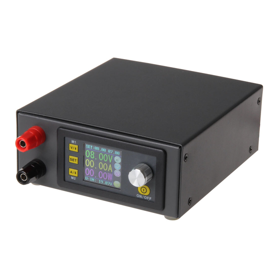
DPS CASE
Case for the JT-DPS5015, JT-DPS5005 and JT-DPH5005
1. GENERAL INFORMATION
Dear customer,
thank you for purchasing our product. The following is a manual for the
assembling of a case for DPS5015, DPS5005 and DPH5005.
Should you have any problems, do not hesitate to contact us.
Advertisement

Subscribe to Our Youtube Channel
Related Manuals for Joy-it DPS CASE


Summary of Contents for Joy-it DPS CASE
- Page 1 DPS CASE Case for the JT-DPS5015, JT-DPS5005 and JT-DPH5005 1. GENERAL INFORMATION Dear customer, thank you for purchasing our product. The following is a manual for the assembling of a case for DPS5015, DPS5005 and DPH5005. Should you have any problems, do not hesitate to contact us.
- Page 2 2. COMPONENTS 3. ASSEMBLY OF THE CASE Prepare the needed components. To facilitate the assembling, you should begin with the small board from the case. You have to solder a fan on the board, also a toggle switch and a cable have to be pursued to the mainboard.
- Page 3 The red cable (+) must be soldered on “+“ and the black one (-) on the board at “-“. Pull beforehand the stripped ends through the holes and solder from both sides. Attention: Cut the cable cores on the backside with a side cutter off so that they will not cause a short later! First must be the switch soldered that the lab power supply can be switched...
- Page 4 The other end of the cable must be soldered on to the small board. Have in mind the different polarities of both cables. = „+“ and Black = „-“ Now you can solder the switch. Have in mind that the cables must go later on through the case or attach the switch beforehand.
- Page 5 As soon as you have finished, you begin to prepare the cables for the output. For that, you need again the cables with the bigger diameter and strip down about 5 mm on both sides. Attach forked cable lugs on both sides. Now you can install the fan from the inside of the case.
- Page 6 In the end, you only have to connect the display. You have to connect two cables with the mainboard. One cable is for the display (“LCD“) and one for the keys (“KEY“). The ports for the cables are marked on the board as well as on the display.
- Page 7 But the place of the port which is used for the modules, depends on the model. You should note that the case could affect the range of the BT module. The necessary software can be downloaded from our website: www.joy-it.net...
- Page 8 5. JT-DPS5005 The JT-DPS-Case can be used with our JT-DPS5015, our JT-DPS5005 and our JT-DPH5005. The JT-DPS5005 does not have a separate board like the JT-DPS5015 and the JT-DPH5005, the assembly of the case is a little bit different. The input voltage and the output voltage of the case must be plugged in to the intented 4-pole PCB plug.
- Page 9 We are there for you after your purchase. If any questions remain open or any problems arise, we are available by e-mail, telephone and ticket support system. E-mail: service@joy-it.net Ticket-system: http://support.joy-it.net Telephone: +49 (0)2845 98469 – 66 (10 - 17 o‘clock) For more information visit our website: www.joy-it.net...
Need help?
Do you have a question about the DPS CASE and is the answer not in the manual?
Questions and answers