
Subscribe to Our Youtube Channel
Related Manuals for National Instruments PXI Express PXIe-1075


Summary of Contents for National Instruments PXI Express PXIe-1075
- Page 1 (217) 352-9330 | Click HERE Find the National Instruments PXIe-1075 at our website:...
- Page 2 PXI Express NI PXIe-1075 User Manual NI PXIe-1075 User Manual January 2017 372537C-01 Artisan Technology Group - Quality Instrumentation ... Guaranteed | (888) 88-SOURCE | www.artisantg.com...
- Page 3 NI Services appendix. To comment on NI documentation, refer to the NI website at and enter the Info Code ni.com/info feedback © 2008–2017 National Instruments. All rights reserved. Artisan Technology Group - Quality Instrumentation ... Guaranteed | (888) 88-SOURCE | www.artisantg.com...
- Page 4 National Instruments Corporation. National Instruments respects the intellectual property of others, and we ask our users to do the same. NI software is protected by copyright and other intellectual property laws. Where NI software may be used to reproduce software or other materials belonging to others, you may use NI software only to reproduce materials that you may reproduce in accordance with the terms of any applicable license or other legal restriction.
- Page 5 The ExpressCard ™ word mark and logos are owned by PCMCIA and any use of such marks by National Instruments is under license. The mark LabWindows is used under a license from Microsoft Corporation. Windows is a registered trademark of Microsoft Corporation in the United States and other countries.
-
Page 6: Table Of Contents
Power Inhibit Switch LED Indicator ................2-8 Remote Voltage Monitoring and Control ................. 2-9 Inhibit Mode Switch ......................2-10 PXI_CLK10 Rear Connectors ..................2-11 © National Instruments | v Artisan Technology Group - Quality Instrumentation ... Guaranteed | (888) 88-SOURCE | www.artisantg.com... - Page 7 Contents PXI Express System Configuration with MAX..............2-11 PXI-1 System Configuration ..................2-12 Trigger Configuration in MAX................. 2-12 PXI Trigger Bus Routing..................2-13 Using System Configuration and Initialization Files............2-13 Chapter 3 Maintenance Service Interval ......................... 3-1 Preparation ........................3-1 Cleaning ..........................3-1 Interior Cleaning .......................
-
Page 8: About This Manual
• PCI Express Base Specification, Revision 1.1, PCI Special Interest Group • PXI-5 PXI Express Hardware Specification, Revision 2.0, PXI Systems Alliance © National Instruments | vii Artisan Technology Group - Quality Instrumentation ... Guaranteed | (888) 88-SOURCE | www.artisantg.com... -
Page 9: Getting Started
Getting Started This chapter describes the key features of the NI PXIe-1075 chassis and lists the kit contents and optional equipment you can order from National Instruments. Unpacking Carefully inspect the shipping container and the chassis for damage. Check for visible damage to the metal work. -
Page 10: Key Features
If you are missing any of the items listed in Table 1-1 or Table 1-2, or if you have the incorrect AC power cable, contact National Instruments. Key Features The NI PXIe-1075 chassis combines a high-performance 18-slot PXI Express backplane with a high-output power supply and a structural design that has been optimized for maximum usability in a wide range of applications. - Page 11 Front and rear rack-mount kits • Replacement power supply shuttle • EMC filler panels • Slot blockers for improved cooling performance • Factory installation services © National Instruments | 1-3 Artisan Technology Group - Quality Instrumentation ... Guaranteed | (888) 88-SOURCE | www.artisantg.com...
-
Page 12: Chassis Description
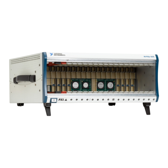
Chapter 1 Getting Started Chassis Description Figures 1-1 and 1-2 show the key features of the NI PXIe-1075 chassis front and back panels. Figure 1-1 shows the front view of the NI PXIe-1075. Figure 1-2 shows the rear view of the NI PXIe-1075. -
Page 13: Optional Equipment
10 MHz REF IN BNC 14 Air Filter Retainer Optional Equipment Contact National Instruments to order the following options for the NI PXIe-1075 chassis. EMC Filler Panels Optional EMC filler panel kits are available from National Instruments. Rack Mount Kit There are two optional kits for mounting the PXIe-1075 chassis into a rack. -
Page 14: Ni Pxie-1075 Chassis Backplane Overview
Chapter 1 Getting Started NI PXIe-1075 Chassis Backplane Overview This section provides an overview of the backplane features for the NI PXIe-1075 chassis. Interoperability with CompactPCI The design of the NI PXIe-1075 provides you the flexibility to use the following devices in a single PXI Express chassis: •... -
Page 15: Hybrid Peripheral Slots
A CompactPCI Express Type-2 Peripheral with x4 or x1 PCI Express link to the system slot or through a PCIe switch to the system slot. © National Instruments | 1-7 Artisan Technology Group - Quality Instrumentation ... Guaranteed | (888) 88-SOURCE | www.artisantg.com... -
Page 16: System Timing Slot
Chapter 1 Getting Started System Timing Slot The System Timing Slot is slot 10. The system timing slot will accept the following peripheral modules: • A PXI Express System Timing Module with x4 or x1 PCI Express link to the system slot through a PCIe switch. -
Page 17: Pxi Local Bus
(user-specified line and directional assignments) can be configured through Measurement & Automation Explorer (MAX). Dynamic routing of triggers (automatic line assignments) is supported through certain National Instruments drivers like NI-DAQmx. Although any trigger line may be routed in either direction, it cannot be Note routed in more than one direction at a time. -
Page 18: System Reference Clock
Chapter 1 Getting Started System Reference Clock The PXIe-1075 chassis supplies PXI_CLK10, PXIe_CLK100 and PXIe_SYNC100 to every peripheral slot with an independent driver for each signal. An independent buffer (having a source impedance matched to the backplane and a skew of less than 1 ns between slots) drives PXI_CLK10 to each peripheral slot. - Page 19 Refer to Appendix A, Specifications, for the specification information for the 10 MHz REF OUT signal on the rear panel of the chassis. © National Instruments | 1-11 Artisan Technology Group - Quality Instrumentation ... Guaranteed | (888) 88-SOURCE | www.artisantg.com...
- Page 20 Chapter 1 Getting Started PXIe_SYNC_CTRL PXIe_SYNC100 is by default a 10 ns pulse synchronous to PXI_CLK10. The frequency of PXIe_SYNC100 is 10/n MHz, where n is a positive integer. The default for n is 1, giving PXIe_SYNC100 a 100 ns period. However, the backplane allows n to be programmed to other integers.
-
Page 21: Installation And Configuration
• Part Replacement—Only service this equipment with parts that are exact replacements, both electrically and mechanically. Contact National Instruments for replacement part information. Installation of parts with those that are not direct replacements may cause harm to personnel operating the chassis. Furthermore, damage or fire may occur if replacement parts are unsuitable. -
Page 22: Chassis Cooling Considerations
Chapter 2 Installation and Configuration Chassis Cooling Considerations The NI PXIe-1075 chassis is designed to operate on a bench or in an instrument rack. Regardless of the configuration you must provide the cooling clearances as outlined in the following sections. Providing Adequate Clearance The primary cooling exhaust vent for the NI PXIe-1075 is on the top of the chassis. -
Page 23: Chassis Ambient Temperature Definition
Specifications. If the temperature exceeds the stated spec the power switch LED will blink green, as discussed in the Power Inhibit Switch LED Indicator section of this chapter. © National Instruments | 2-3 Artisan Technology Group - Quality Instrumentation ... Guaranteed | (888) 88-SOURCE | www.artisantg.com... -
Page 24: Setting Fan Speed
Chapter 2 Installation and Configuration Setting Fan Speed The fan-speed selector switch is on the rear panel of the NI PXIe-1075 chassis. Refer to Figure 1-2, Rear View of the NI PXIe-1075 Chassis, to locate the fan-speed selector switch. Select High for maximum cooling performance or Auto for improved acoustic performance. When set to Auto, the fan speed is determined by chassis intake air temperature. -
Page 25: Connecting To Power Source
Slide the system controller to the rear of the chassis, making sure that the injector/ejector handle is pushed down as shown in Figure 2-3. © National Instruments | 2-5 Artisan Technology Group - Quality Instrumentation ... Guaranteed | (888) 88-SOURCE | www.artisantg.com... - Page 26 Chapter 2 Installation and Configuration Figure 2-3. Installing a PXIe System Controller NI PXI Express System Controller Injector/Ejector Handle NI PXIe-1075 Chassis System Controller Front Panel Mounting Screws (4x) When you begin to feel resistance, pull up on the injector/ejector handle to seat the system controller fully into the chassis frame.
-
Page 27: Installing Peripheral Modules
AC power cord grounds the chassis and protects it from electrical damage while you install the module. Ensure that the chassis is powered off. © National Instruments | 2-7 Artisan Technology Group - Quality Instrumentation ... Guaranteed | (888) 88-SOURCE | www.artisantg.com... -
Page 28: Power Inhibit Switch Led Indicator
Chapter 2 Installation and Configuration Install a module into a chassis slot by first placing the module card PCB into the front of the card guides (top and bottom), as shown in Figure 2-5. Slide the module to the rear of the chassis, making sure that the injector/ejector handle is pushed down as shown in Figure 2-5. -
Page 29: Remote Voltage Monitoring And Control
When connecting digital voltmeter probes to the rear 9-pin D-SUB Caution (DB-9) connector, be careful not to short the probe leads together. Doing so could damage the power supply. © National Instruments | 2-9 Artisan Technology Group - Quality Instrumentation ... Guaranteed | (888) 88-SOURCE | www.artisantg.com... -
Page 30: Inhibit Mode Switch
Chapter 2 Installation and Configuration You can use a digital voltmeter to ensure all voltage levels in the NI PXIe-1075 chassis are within the allowable limits. Referring to Table 2-2, connect one lead of the voltmeter to a supply pin on the remote voltage monitoring connector (9-pin D-SUB) on the rear panel. Refer to Table 2-1 for a pinout diagram of the remote voltage monitoring connector. -
Page 31: Pxi_Clk10 Rear Connectors
PXI triggers, refer to KnowledgeBase 3TJDOND8 at ni.com/support The configuration steps for single or multiple-chassis systems are the same. Figure 2-6. Multichassis Configuration in MAX © National Instruments | 2-11 Artisan Technology Group - Quality Instrumentation ... Guaranteed | (888) 88-SOURCE | www.artisantg.com... -
Page 32: Trigger Configuration In Max
Dynamic reservation/routing/deallocation is on the fly within a user program based upon National Instruments APIs such as NI-DAQmx. Static reservation of trigger lines can be implemented by the user in MAX through the Triggers tab. -
Page 33: Pxi Trigger Bus Routing
Click the Apply button. PXI Trigger Bus Routing Some National Instruments chassis, such as the PXI-1075 and the PXI-1044/1045, have the capability to route triggers from one bus to others within the same chassis using the Trigger Routing tab in MAX, as shown in Figure 2-6. - Page 34 Chapter 2 Installation and Configuration Device drivers and other utility software read the file to obtain system pxisys.ini information. The device drivers should have no need to directly read the file. chassis.ini For detailed information regarding initialization files, refer to the PXI Express specification at www.pxisa.org 2-14 | ni.com Artisan Technology Group - Quality Instrumentation ...
-
Page 35: Maintenance
Use a dry, low-velocity stream of air to clean the interior of the chassis. Use a soft-bristle brush for cleaning around components. © National Instruments | 3-1 Artisan Technology Group - Quality Instrumentation ... Guaranteed | (888) 88-SOURCE | www.artisantg.com... -
Page 36: Exterior Cleaning
Chapter 3 Maintenance Exterior Cleaning Clean the exterior surfaces of the chassis with a dry lint-free cloth or a soft-bristle brush. If any dirt remains, wipe with a cloth moistened in a mild soap solution. Remove any soap residue by wiping with a cloth moistened with clear water. -
Page 37: Replacing The Modular Power Supply Shuttle
Using a Phillips screwdriver, remove the screws. Pull on the two rear handles of the power supply shuttle to remove it from the back of the chassis. © National Instruments | 3-3 Artisan Technology Group - Quality Instrumentation ... Guaranteed | (888) 88-SOURCE | www.artisantg.com... -
Page 38: Installation
Chapter 3 Maintenance Installation Ensure that there is no visible damage to the new power supply shuttle. Verify that the housing and connector on the new power supply shuttle have no foreign material inside. Remove the protective cap on the PXI_CLK10 connector. Install the new power supply shuttle into the opening on the rear of the chassis. -
Page 39: Appendix A Specifications
D-SUB 9-pin connector and power mode switch to control the internal chassis power supply. For The operating range is guaranteed by design. © National Instruments | A-1 Artisan Technology Group - Quality Instrumentation ... Guaranteed | (888) 88-SOURCE | www.artisantg.com... - Page 40 Chapter A Specifications more information, refer to the Inhibit Mode Switch section of Chapter 2, Installation and Configuration. DC Output DC current capacity (I Voltage Maximum Current +3.3 V 60 A +5 V 48 A +12 V 62 A -12 V 2.0 A Maximum total usable power is 791 W.
- Page 41 Along both sides and top of chassis Power supply cooling system Forced air circulation through two integrated fans Power supply cooling intake Right side of chassis © National Instruments | A-3 Artisan Technology Group - Quality Instrumentation ... Guaranteed | (888) 88-SOURCE | www.artisantg.com...
- Page 42 Chapter A Specifications Power supply cooling exhaust Left side of chassis Clearance for intake/exhaust vents 1.75 in. (44.45 mm) for top and side vents 3.00 in. (76.20 mm) for back vents Maximum fan cleaning interval 6 months Fan filter material 30 ppi, 3/32 in.
- Page 43 UL 61010-1, CSA 61010-1 For UL and other safety certifications, refer to the product label or the Online Note Product Certification section. © National Instruments | A-5 Artisan Technology Group - Quality Instrumentation ... Guaranteed | (888) 88-SOURCE | www.artisantg.com...
- Page 44 Certification column. Environmental Management National Instruments is committed to designing and manufacturing products in an environmentally responsible manner. NI recognizes that eliminating certain hazardous substances from our products is beneficial not only to the environment but also to NI customers.
- Page 45 5 ps RMS phase-jitter (10 Hz-1 MHz range) Duty-factor 45 to 55% Unloaded signal swing 3.3 V ±0.3 V For other specifications refer to the PXI-1 Hardware Specification. Note © National Instruments | A-7 Artisan Technology Group - Quality Instrumentation ... Guaranteed | (888) 88-SOURCE | www.artisantg.com...
- Page 46 Chapter A Specifications 100 MHz System Reference Clock: PXIe_CLK100 and PXIe_SYNC100 Maximum slot-to-slot skew 100 ps Accuracy ±25 ppm max. (guaranteed over the operating temperature range) Maximum jitter 3 ps RMS phase-jitter (10 Hz to 12 kHz range) 2 ps RMS phase-jitter (12 kHz to 20 MHz range) Duty-factor for PXIe_CLK100 45 to 55% Absolute single-ended voltage swing...
- Page 47 System Timing Slot Note section of Chapter 1, Getting Started. For other specifications, the NI PXIe-1075 complies with the PXI-5 PXI Express Hardware Specification. © National Instruments | A-9 Artisan Technology Group - Quality Instrumentation ... Guaranteed | (888) 88-SOURCE | www.artisantg.com...
- Page 48 Chapter A Specifications Mechanical Overall dimensions Standard chassis Height 6.97 in. (177.1 mm) Width 18.30 in. (464.8 mm) Depth 18.40 in. (467.4 mm) 0.57 in. (14.5 mm) is added to height when feet are installed. When tilted with Note front feet extended on table top, height is increased approximately 2.08 in. (52.8 mm) in front and 0.583 in.
- Page 49 1.37 1.58 (34.8) (40.1) 10.21 (259.1) Front of 1.84 3.54 PXI Card (46.8) (90.0) 0.30 (7.25) 2.12 (53.8) 17.11 (434.6) 3.19 (81.1) © National Instruments | A-11 Artisan Technology Group - Quality Instrumentation ... Guaranteed | (888) 88-SOURCE | www.artisantg.com...
- Page 50 Chapter A Specifications Figure A-2. NI PXIe-1075 Chassis Dimensions (Bottom) Dimensions are in inches (millimeters) 12.700 (322.58) 2.524 (64.11) 15.504 (393.8) 1.017 (25.83) A-12 | ni.com Artisan Technology Group - Quality Instrumentation ... Guaranteed | (888) 88-SOURCE | www.artisantg.com...
- Page 51 For more information on rack mounting the NI PXIe-1075 chassis, refer to the printed installation guide included with your rack mount kit. © National Instruments | A-13 Artisan Technology Group - Quality Instrumentation ... Guaranteed | (888) 88-SOURCE | www.artisantg.com...
- Page 52 For more detailed information, refer to the PXI-5 PXI Express Hardware Specification, Revision 2.0. Contact the PXI Systems Alliance for a copy of the specification. © National Instruments | B-1 Artisan Technology Group - Quality Instrumentation ... Guaranteed | (888) 88-SOURCE | www.artisantg.com...
- Page 53 Appendix B Pinouts System Controller Slot Pinouts Figure B-1. PXI Express System Controller Slot Layout XP4 Connector XP2 Connector XP3 Connector XP1 Connector B-2 | ni.com Artisan Technology Group - Quality Instrumentation ... Guaranteed | (888) 88-SOURCE | www.artisantg.com...
- Page 54 Table B-1. XP4 Connector Pinout for the System Controller Slot 5Vaux SYSEN# WAKE# ALERT# PXI_TRIG3 PXI_TRIG4 PXI_TRIG5 PXI_TRIG6 PXI_TRIG2 PXI_STAR PXI_CLK10 PXI_TRIG1 PXI_TRIG0 PXI_TRIG7 PXI_LBR6 Table B-2. XP3 Connector Pinout for the System Controller Slot PWR_OK PS_ON# LINKCAP PWRBTN# SMBDAT SMBCLK 4RefClk+ 4RefClk-...
- Page 55 Table B-2. XP3 Connector Pinout for the System Controller Slot (Continued) 1PETp3 1PETn3 1PERp3 1PERn3 2PETp0 2PETn0 2PETp1 2PETn1 2PERp1 2PERn1 2PERp0 2PERn0 2PETp2 2PETn2 2PERp2 2PERn2 2PETp3 2PETn3 3PETp0 3PETn0 3PERp0 3PERn0 2PERp3 2PERn3 Table B-3. XP2 Connector Pinout for the System Controller Slot 3PETp1 3PETn1 3PERp1...
- Page 56 Signals 3.3V System Timing Slot Pinouts Figure B-2. PXI Express System Timing Slot Layout XP4 Connector TP2 Connector XP3 Connector TP1 Connector © National Instruments | B-5 Artisan Technology Group - Quality Instrumentation ... Guaranteed | (888) 88-SOURCE | www.artisantg.com...
- Page 57 Table B-5. XP4 Connector Pinout for the System Timing Slot SYSEN# WAKE# ALERT# 3.3V 3.3V 3.3V PXI_TRIG3 PXI_TRIG4 PXI_TRIG5 PXI_TRIG6 PXI_TRIG2 ATNLED PXI_CLK10_IN PXI_CLK10 PXI_TRIG1 PXI_TRIG0 ATNSW# PXI_TRIG7 PXIe_SYNC_CTRL PXI_LBL6 PXI_LBR6 Table B-6. XP3 Connector Pinout for the System Timing Slot PXIe_CLK100 PXIe_ PXIe_...
- Page 58 Table B-6. XP3 Connector Pinout for the System Timing Slot (Continued) 1PETp2 1PETn2 1PERp2 1PERn2 1PERp1 1PERn1 1PETp3 1PETn3 1PERp3 1PERn3 1PETp4 1PETn4 1PETp5 1PETn5 1PERp5 1PERn5 1PERp4 1PERn4 1PETp6 1PETn6 1PERp6 1PERn6 1PETp7 1PETn7 1PERp7 1PERn7 Table B-7. TP2 Connector Pinout for the System Timing Slot PXIe_ PXIe_ PXIe_...
- Page 59 Table B-7. TP2 Connector Pinout for the System Timing Slot (Continued) PXIe_ PXIe_ PXI_STAR6 PXI_STAR7 PXIe_ PXIe_ DSTARB2+ DSTARB2- DSTARB10+ DSTARB10- PXIe_ PXIe_ PXI_STAR8 PXI_STAR9 PXIe_ PXIe_ DSTARA2+ DSTARA2- DSTARC11+ DSTARC11- PXIe_ PXIe_ PXI_ PXI_ PXIe_ PXIe_ DSTARC3+ DSTARC3- STAR10 STAR11 DSTARA11+ DSTARA11-...
- Page 60 Table B-8. TP1 Connector Pinout for the System Timing Slot (Continued) PXIe_ PXIe_ PXIe_ PXIe_ PXIe_ PXIe_ DSTARB5+ DSTARB5- DSTARB16+ DSTARB16- DSTARB13+ DSTARB13- PXIe_ PXIe_ PXIe_ PXIe_ PXIe_ PXIe_ DSTARA5+ DSTARA5- DSTARA7+ DSTARA7- DSTARC14+ DSTARC14- PXIe_ PXIe_ PXI_STAR16 PXIe_ PXIe_ DSTARC6+ DSTARC6- DSTARA14+...
- Page 61 Appendix B Pinouts Hybrid Slot Pinouts Figure B-3. PXI Express System Hybrid Slot Layout XP4 Connector XP3 Connector P1 Connector B-10 | ni.com Artisan Technology Group - Quality Instrumentation ... Guaranteed | (888) 88-SOURCE | www.artisantg.com...
- Page 62 Table B-9. XP4 Connector Pinout for the Hybrid Slot 5Vaux SYSEN# WAKE# ALERT# 3.3V 3.3V 3.3V PXI_TRIG3 PXI_TRIG4 PXI_TRIG5 PXI_TRIG6 PXI_TRIG2 ATNLED PXI_STAR PXI_CLK10 PXI_TRIG1 PXI_TRIG0 ATNSW# PXI_TRIG7 PXI_LBL6 PXI_LBR6 Table B-10. XP3 Connector Pinout for the Hybrid Slot PXIe_ PXIe_ PXIe_ PXIe_...
- Page 63 Table B-10. XP3 Connector Pinout for the Hybrid Slot (Continued) 1PETp2 1PETn2 1PERp2 1PERn2 1PERp1 1PERn1 1PETp3 1PETn3 1PERp3 1PERn3 1PETp4 1PETn4 1PETp5 1PETn5 1PERp5 1PERn5 1PERp4 1PERn4 1PETp6 1PETn6 1PERp6 1PERn6 1PETp7 1PETn7 1PERp7 1PERn7 Table B-11. P1 Connector Pinout for the Hybrid Slot REQ64# ENUM# 3.3V...
- Page 64 Table B-11. P1 Connector Pinout for the Hybrid Slot (Continued) DEVSEL# V(I/O) STOP# LOCK# 3.3V FRAME# IRDY# BD_SEL# TRDY# 12 to 14 Key Area AD[18] AD[17] AD[16] C/BE[2]# AD[21] 3.3V AD[20] AD[19] C/BE[3]# IDSEL AD[23] AD[22] AD[26] V(I/O) AD[25] AD[24] AD[30] AD[29] AD[28]...
- Page 65 • System Integration—If you have time constraints, limited in-house technical resources, or other project challenges, National Instruments Alliance Partner members can help. To learn more, call your local NI office or visit ni.com/alliance © National Instruments | C-1...
- Page 66 Appendix C NI Services • Training and Certification—The NI training and certification program is the most effective way to increase application development proficiency and productivity. Visit for more information. ni.com/training – The Skills Guide assists you in identifying the proficiency requirements of your current application and gives you options for obtaining those skills consistent with your time and budget constraints and personal learning preferences.
- Page 67 Equal or less than. Percent. Amperes. Alternating current. ANSI American National Standards Institute. Auto Automatic fan speed control. American Wire Gauge. © National Instruments | G-1 Artisan Technology Group - Quality Instrumentation ... Guaranteed | (888) 88-SOURCE | www.artisantg.com...
- Page 68 Glossary backplane An assembly, typically a printed circuit board, with connectors and signal paths that bus the connector pins. Bayonet Neill Concelman connector; a commonly used coaxial connector. Celsius. Cubic feet per minute. Code of Federal Regulations. Centimeters. CompactPCI An adaptation of the Peripheral Component Interconnect (PCI) Specification 2.1 or later for industrial and/or embedded applications requiring a more robust mechanical form factor than desktop PCI.
- Page 69 International Electrotechnical Commission; an organization that sets international electrical and electronics standards. IEEE Institute of Electrical and Electronics Engineers. Mainframe peak current. © National Instruments | G-3 Artisan Technology Group - Quality Instrumentation ... Guaranteed | (888) 88-SOURCE | www.artisantg.com...
- Page 70 Glossary Inches. inhibit To turn off. jitter A measure of the small, rapid variations in clock transition times from their nominal regular intervals. Units: seconds RMS. Kilograms. Kilometers. Pounds. Light emitting diode. line regulation The maximum steady-state percentage that a DC voltage output will change as a result of a specified change in input AC voltage (step change from 90 VAC to 132 VAC or 180 VAC to 264 VAC).
- Page 71 Installing such a device into any other slot can damage the device, the PXI backplane, or both. © National Instruments | G-5 Artisan Technology Group - Quality Instrumentation ... Guaranteed | (888) 88-SOURCE | www.artisantg.com...
- Page 72 Glossary system reference A 10 MHz clock, also called PXI_CLK10, that is distributed to all clock peripheral slots in the chassis, as well as a BNC connector on the rear of chassis labeled 10 MHz REF OUT. The system reference clock can be used for synchronization of multiple modules in a measurement or control system.
- Page 73 MAX (figure), 2-11 configuration. See installation, configuration, connecting safety ground, 2-4 and operation filler panel installation, 2-4 connector pinouts. See pinouts © National Instruments | I-1 Artisan Technology Group - Quality Instrumentation ... Guaranteed | (888) 88-SOURCE | www.artisantg.com...
- Page 74 Index installing a PXI Express system controller, 2-5 NI PXIe-1075 figure, 2-6 architecture, backplane, 1-6 module installation backplane overview, 1-6 CompactPCI or PXI modules fan speed, setting, 2-4 (figure), 2-8 front view (figure), 1-4 peripheral module installation, 2-7 hybrid peripheral slots, 1-7 figure, 2-8 installation.
- Page 75 XP2 connector (table), B-4 safety specifications, A-5 XP3 connector (table), B-3 service interval, 3-1 XP4 connector (table), B-3 setting fan speed, 2-4 © National Instruments | I-3 Artisan Technology Group - Quality Instrumentation ... Guaranteed | (888) 88-SOURCE | www.artisantg.com...
- Page 76 Index system reference clock, 1-10 default behavior (figure), 1-10 specifications, A-7 system timing slot description, 1-8 pinouts TP1 connector (table), B-8 TP2 connector (table), B-7 XP3 connector (table), B-6 XP4 connector (table), B-6 testing power up, 2-5 trigger bus, 1-9 unpacking the NI PXIe-1075 chassis, 1-1 voltage monitoring connector.
Need help?
Do you have a question about the PXI Express PXIe-1075 and is the answer not in the manual?
Questions and answers