Sign In
Upload
Manuals
Brands
Michell Instruments Manuals
Transmitter
SF82 Series
Michell Instruments SF82 Series Manuals
Manuals and User Guides for Michell Instruments SF82 Series. We have
2
Michell Instruments SF82 Series manuals available for free PDF download: User Manual
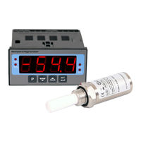
Michell Instruments SF82 Series User Manual (60 pages)
Online Dew-Point Hygrometer
Brand:
Michell Instruments
| Category:
Measuring Instruments
| Size: 3 MB
Table of Contents
Table of Contents
4
Safety
7
Electrical Safety
7
Pressure Safety
7
Toxic Materials
7
Repair and Maintenance
7
Calibration
7
Safety Conformity
7
Abbreviations
8
Warnings
8
1 Introduction
9
Figure 1 SF82 Online Monitor and Transmitter
9
Features
10
2 Installation
11
Unpacking the Instrument
11
Figure 2 Unpacking Method
11
Unpacking the SF82 Transmitter
12
Unpacking the Monitor
12
Figure 3 Transmitter Unpacking Method
12
Figure 4 Monitor Unpacking Method
12
Accessories Pack
13
SF82 Online Components
13
Figure 5 Accessories Pack
13
Figure 6 SF82 Online Components
13
Monitor
14
Fault Conditions
14
Figure 7 Monitor Panel Layout
14
Monitor Controls and Indicators
15
Table 1 Monitor Front Panel Controls and Indicators
15
Electrical Connections
16
Figure 8 Monitor Rear Panel Connections
17
Table 2 Summary of Electrical Connections
17
AC Power Supply Input
18
Figure 9 AC Power Supply Connections
18
DC Power Supply Input (Not Available at Present)
19
Figure 10 DC Power Supply Connections
19
Transmitter Connection
20
Figure 11 Transmitter Connections
20
Signal Output Connections
21
2.3.7.1 Alarm Outputs
21
2.3.7.2 Re-Transmission Output
21
2.3.7.3 RS485 Modbus RTU Communications Port
21
Figure 12 Digital Communications Port
21
Mounting the Monitor
22
Figure 13 Mounting the Monitor
22
SF82 Transmitter
23
SF82 DIN 43650 Connector Version
23
Figure 14 SF82 Transmitter
23
2.4.1.1 Electrical Connections
24
2.4.1.2 Cable Connection to Transmitter
24
Figure 15 Connector Installation
24
2.4.1.3 Sensor Cable Self-Assembly
25
Figure 16 Connector Terminal Block Removal
25
Figure 17 Cable Assembly
25
SF82 M12 Connector Version
26
2.4.2.1 Electrical Connections
26
Figure 18 Sensor Connector Installation
26
2.4.2.2 SF82 M12 Cables
27
Cable Selection for Self-Assembled Cables
27
Maximum Loop Resistance Vs Supply Voltage
27
Figure 19 Maximum Load of SF82 - Including Cable Resistance
27
Transmitter Mounting
28
5/8" 18 UNF Version
28
3/4" - 16 UNF Version
28
G1/2" BSPP Version
28
Transmitter Mounting - Sample Block (Optional)
29
Figure 20 Transmitter Mounting - Sensor Block
29
Transmitter Mounting - Direct Pipeline Connection
30
Figure 21 Transmitter Mounting - Pipe or Duct
30
Transmitter Mounting - with Additional Process Connection Adapter
31
Figure 22 Transmitter Mounting with Adapter
31
Mounting the Sample Block and Transmitter
32
Sample Block Gas Connections
32
Figure 23 Sample Block Gas Connections
32
3 Operation
34
General Operational Information
34
Preparation for Operation
35
First-Time Operation
35
Figure 24 Typical Display
35
Monitor Setup
36
Change Alarm Type (High/Low)
36
Figure 25 Change Alarm Switching Logic
37
Change Alarm Set-Points
38
Figure 26 Set-Up Alarm Levels
38
Analog Output: Change from 4-20Ma to 0-20Ma
39
Monitor Input Range
39
Figure 27 Configure Analog Output
39
Set the Monitor to °F Dew-Point Mode
40
Figure 28 Span and Unit Settings
40
Set the Monitor to Ppm Mode (Not Available)
41
Monitor Limits When Unit Scaled to Ppm (Not Available)
42
Figure 29 Set-Up Monitor (to Read Ppm )
42
Alarm Set-Point Limit Configuration
43
Figure 30 Set-Up Alarm Set-Point Limits
43
Digital Communication Parameters Set-Up
44
Figure 31 Set-Up Data Communications Parameters
45
Modbus RTU over RS485 Communications
46
4 Good Measurement Practice
50
General Operational Guidelines
50
Figure 32 Installation Location
50
Figure 33 Indication of Dead Space
50
Maintenance and Calibration
52
Clean Monitor
52
Appendix A Technical Specifications
54
Figure 34 Dimensions
55
Dimensions
55
Appendix B Quality, Recycling & Warranty Information
57
Appendix C Return Document & Decontamination Declaration
59
Advertisement
Michell Instruments SF82 Series User Manual (38 pages)
Dew-Point Transmitter
Brand:
Michell Instruments
| Category:
Transmitter
| Size: 2 MB
Table of Contents
Table of Contents
4
Safety
6
Electrical Safety
6
Pressure Safety
6
Toxic Materials
6
Repair and Maintenance
6
Calibration
6
Safety Conformity
7
Abbreviations
7
Warnings
7
1 Introduction
8
2 Installation
9
Unpacking the Instrument
9
Preparation of the Sensor Cable
10
Figure 1 Connector Terminal Block Removal
10
Figure 2 Wiring Connections
10
Figure 3 Sensor Connector Installation
11
Figure 4 Cable Connections
11
Cable Connection
12
Electrical Schematic
12
Figure 5 Connector Installation
12
Figure 6 2-Wire Connection Diagram
12
Digital Communications (M12 Version Only)
13
Electrical Boundaries
13
Transmitter Installatiom
13
Sampling Considerations
13
Figure 7 Maximum Load of SF82 - Including Cable Resistance
13
Figure 8 Installation Location
14
Figure 9 Installation Location
15
Good Measuring Practice
16
Figure 10 Transmitter Mounting - Sensor Block
16
Figure 11 Material Permeability Comparison
16
Transmitter Mounting
19
Figure 12 Transmitter Mounting - Pipe or Duct
19
Figure 13 Transmitter Mounting with Adapter
21
Appendices
23
Appendix A
24
Technical Specifications
24
Product Dimensions
26
Appendix B
30
Quality, Recycling & Warranty Information
30
Appendix C
32
Return Document & Decontamination Declaration
32
Appendix D
34
Modbus Register Map
34
Register Address
35
Advertisement
Related Products
Michell Instruments SF52
Michell Instruments SF82 M12
Michell Instruments SF82 MiniDIN 43650
Michell Instruments SF72
Michell Instruments S8000
Michell Instruments S904
Michell Instruments S904D
Michell Instruments S4000 TRS
Michell Instruments S-535
Michell Instruments DT722
Michell Instruments Categories
Measuring Instruments
Transmitter
Analytical Instruments
Test Equipment
Laboratory Equipment
More Michell Instruments Manuals
Login
Sign In
OR
Sign in with Facebook
Sign in with Google
Upload manual
Upload from disk
Upload from URL