Table of Contents
Advertisement
Quick Links
Advertisement
Table of Contents

Related Manuals for Motorline professional KVM25


Summary of Contents for Motorline professional KVM25
- Page 1 KVM25 USER’S AND INSTALLER’S MANUAL V3.0 REV. 03/2017...
-
Page 2: Table Of Contents
00. CONTENTS 01. SAFETY INSTRUCTIONS INDEX STANDARDS TO FOLLOW ATTENTION: 01. SAFETY INSTRUCTIONS STANDARDS TO FOLLOW This product is certified in accordance with European Community (EC) safety standards. 02. THE PACKAGE INSIDE THE PACKAGE This product complies with Directive 2011/65/EU of the European Parliament and of the Council, 03. -
Page 3: The Package
The automatism unlock function allows the user to open and close the gate manually, wi- thout having to remove the motor from the installation site. This funcionality is specially important in emergency cases and/or power cuts. • 01 automatism KVM25 • 01 pinion for Ø25mm shaft • 01 maneuver board •... -
Page 4: Technical Specifications 3A
04. INSTALLATION TECHNICAL SPECIFICATIONS PRE-INSTALLATION INFO KVM25 specifications are as follow: For a proper installation and a durable performance of KVM25, be aware of the following parameters: • Power Supply AC 230V 50/60Hz • Please read all steps of this manual at least once, so that you know the full process before •... -
Page 5: Automatism Installation 4A
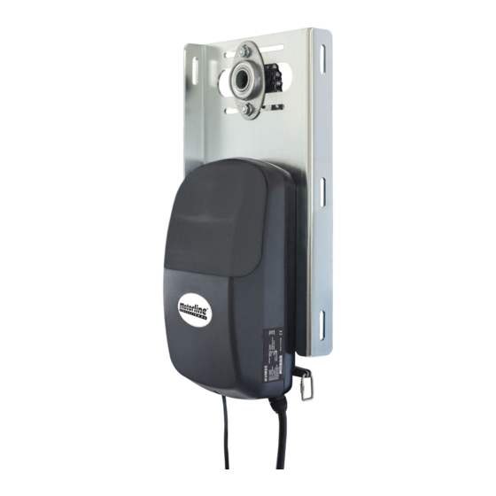
04 - Slightly loosen the bearing bracket’s In the illustrated diagrams below and on the following page, are represented the procedures for proper installation of the motor KVM25. screws (left),to be able to move it sideways. 05 - Pull the metal plate to the wall and se- cure with the screws. - Page 6 Place the screws on the motor in order to support it on the metal plate, without tightening them completely, so that you are able to adjust the automatism. LEGEND: • motor KVM25 • support plate • chain • pinion for Ø25mm shaft •...
-
Page 7: Programming
PROGRAMMING LIMIT SWITCHES In the illustrated diagrams below and on the following page are represented the procedures for proper programming of the motor KVM25 limit switches, once installed on the gate. 05 - Move the plastic piece until hear a click 06 - Manually move the door to the open from the micro.
Need help?
Do you have a question about the KVM25 and is the answer not in the manual?
Questions and answers