Table of Contents
Advertisement
Advertisement
Table of Contents

Related Manuals for Motorline professional MC52


Summary of Contents for Motorline professional MC52
- Page 1 MC52 MC52 USER/INSTALLER MANUAL v1.5 REV. 05/2020...
-
Page 2: Table Of Contents
00. CONTENT 01. SAFETY INSTRUCTIONS INDEX ATTENTION: 01. SAFETY INSTRUCTIONS This product is certified in accordance with European Community (EC) safety standards. 02. THE CONTROL BOARD TECHNICAL SPECIFICATIONS LEDs This product complies with Directive 2011/65/EU of the CONNECTORS European Parliament and of the Council, of 8 June 2011, on the restriction of the use of certain hazardous substances in 03. -
Page 3: Safety Instructions
01. SAFETY INSTRUCTIONS GENERAL WARNINGS • Children shouldn’t play with the product or opening devices to avoid the motorized door or gate from being triggered involuntarily. • This manual contains very important safety and usage information. very important. Read all instructions carefully before beginning the WARNINGS FOR TECHNICIANS installation/usage procedures and keep this manual in a safe place that it can be consulted whenever necessary. - Page 4 01. SAFETY INSTRUCTIONS RESPONSABILITY September 2009. • Attach the permanent label for the manual release as close as possible • Supplier disclaims any liability if: to the release mechanism. • Product failure or deformation result from improper installation • Disconnect means, such as a switch or circuit breaker on the electrical use or maintenance! panel, must be provided on the product’s fixed power supply leads in •...
-
Page 5: Technical Specifications 4A
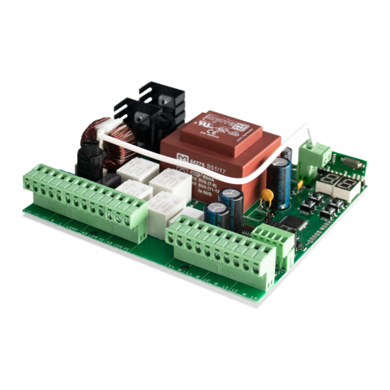
02. CONTROL BOARD 02. CONTROL BOARD TECHNICAL SPECIFICATIONS CONNECTORS The MC52 is a single-phase control board with built-in radio control system designed for the Make sure which version you are using (110Vac or 230Vac). automation of swing gates. 110V version 230V version 01 •... -
Page 6: Installation
03. INSTALLATION INSTALLATION MAP If you activate the EL option in the E5 menu, Antenna the electric lock must not be powered by the control board. To do this, use an external power supply to power the electric lock. Pushbutton or Key Selector Exterior Photocells* Interior Photocells*... -
Page 7: Programming
03. INSTALLATION 04. PROGRAMMING BASE INSTALLATION PROCESS PROGRAMMING AND DELETE TRANSMITTERS Transmitter programming for total opening. The installation process assumes that the gate already has mechanical or electrical limit switches installed. Transmitter programming for pedestrian opening. 01 • Connect all accessories according to the connections diagram (page 5). •... -
Page 8: P Menus 7A
04. PROGRAMMING 04. PROGRAMMING P MENUS E MENUS • We can only enter programming with the gate stopped (electrically). MAX. MIN. FACTORY MENU FUNCTION STATE PAGE • To access the P menu press the MENU key for 3 sec. PROGRAMMABLE VALUE •... - Page 9 04. PROGRAMMING 04. PROGRAMMING P0 - P1 P2 - P3 - P4 COURSE AUTOMATIC PROGRAMMING FORCE ADJUSTMENT This menu allows you to program the motor course manually. This menu allows you to set the force that is injected into the motor when it moves at normal speed. •...
- Page 10 04. PROGRAMMING 04. PROGRAMMING P7 - P8 - P9 P5 - P6 PHOTOCELLS 1 PROGRAMMING OPERATING LOGIC This menu allows you to program the behavior of LE safety (photocell 1). This menu allows to set the operating logic of the automation. Automatic Mode - Whenever there is an order the movement is reversed.
- Page 11 04. PROGRAMMING 04. PROGRAMMING E3 - E4 - E5 - E6 - E7 E0 - E1 - E2 PRESENT MAN COURSE TIME ADJUSTMENT This menu allows you to adjust the working time for opening and closing courses of the two leaves. Enable or disable present man.
-
Page 12: Display Indications
04. PROGRAMMING 05. COMPONENTS TEST E8 - E9 230V/110V MOTOR To detect which components have problems during a sliding automatism installation, RESET - RESET FACTORY VALUES sometimes it's necessary to conduct tests with a direct connection to a 230V power supply. This menu allows you to reset to factory defaults. -
Page 13: Troubleshooting
06. TROUBLESHOOTING INSTRUCTIONS FOR FINAL CONSUMERS INSTRUCTIONS FOR TECHNICIANS Anomaly Procedure Behavior Procedure II Discovering the origin of the problem • Make sure you 1 • Open control box and check if 3 • Disconnect motors from 4 • If the motors work, the 5 •...
Need help?
Do you have a question about the MC52 and is the answer not in the manual?
Questions and answers