Advertisement
Quick Links
Advertisement

Subscribe to Our Youtube Channel
Related Manuals for Motorline professional ECO PLUS RAPID DOOR


Summary of Contents for Motorline professional ECO PLUS RAPID DOOR
- Page 1 ECO PLUS RAPID DOOR USER’S AND INSTALLER’S MANUAL v1.1 REV. 06/2018...
- Page 2 00. CONTENT 01. SAFETY INSTRUCTIONS INDEX STANDARDS TO FOLLOW ATTENTION: 01. SAFETY INSTRUTIONS STANDARDS TO FOLLOW This product is certified in accordance with European Community 02. THE AUTOMATISM (EC) safety standards. COMPONENTS TECHNICAL SPECIFICATIONS INSIDE THE PACKAGE This product complies with Directive 2011/65/EU of the European DIMENSIONS Parliament and of the Council, of 8 June 2011, on the restriction of 03.
- Page 3 01. SAFETY INSTRUCTIONS 01. SAFETY INSTRUCTIONS STANDARDS TO FOLLOW STANDARDS TO FOLLOW • It is important for your safety that these instructions are followed. level or other level of access, , should be followed the minimum safety and • Keep these instructions in a safe place for future reference. health requirements for the use of work equipment workers at work in Directive •...
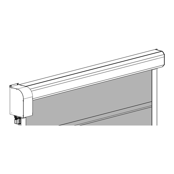
- Page 4 02. AUTOMATISM COMPONENTS 13 • Aluminum safe profile 14 • Tarpaulin 15 • Support plate 1 • Engine cover 2 • Motor 3 • Limit-switches 4 • Crank 5 • Support plate (motor) 6 • Unlocking lever 7 • Control Board 8 •...
- Page 5 02. AUTOMATISM 02. AUTOMATISM TECHNICAL SPECIFICATIONS INSIDE PACKAGE • Manufactured with own profiles of white lacquered aluminum; Inside the package you will find the following components: • It can have up to 3 reinforcing bars; • Suitable for areas with low air pressure. •...
- Page 6 02. AUTOMATISM 03. INSTALLATION DIMENSIONS PRE-INSTALLATION INFO For a proper ECO PLUS RAPID DOOR function, check the following parameters before installing the automatism: Wall • Read all steps at least once in order to get familiar with the installation and configuration process.
- Page 7 03. INSTALLATION 03. INSTALLATION SAFE PROFILE FIXATION SAFE PROFILE FIXATION (FREE DOOR SPACE) 115mm 1 • Apply the safe to the wall, talking into account the horizontal leveling and the measures 2 • Make holes at the marked locations, and then apply the safe profile on the wall and secure indicated (B and C).
- Page 8 03. INSTALLATION 03. INSTALLATION LATERAL GUIDES FIXATION LATERAL GUIDES FIXATION 5 • Fix the lateral guides to the ground using the existing plates. Start by making the holes in the ground using the existing holes on plates for the application of screws. Finally, tightening the screws until the guide is properly secure.
- Page 9 03. INSTALLATION 03. INSTALLATION CONTROL BOARD FIXATION LIMIT-SWICHES ADJUSTMENT NOTE • The red ring must activate it’s micro-switch by the bottom and the white ring must do it by the top, as shown in the picture to the left. Microswitch connections: white close open...
Need help?
Do you have a question about the ECO PLUS RAPID DOOR and is the answer not in the manual?
Questions and answers