Advertisement
Quick Links
Advertisement

Related Manuals for Motorline professional KVM2020


Summary of Contents for Motorline professional KVM2020
- Page 1 KVM2020 INSTALLER AND USER’S MANUAL v1.0 REV. 03/2021...
- Page 2 00. CONTENT 01. SAFETY INSTRUCTIONS INDEX ATTENTION 01. SAFETY INSTRUCTIONS This product is certified in accordance with European Community (EC) safety standards. 02. AUTOMATION This product complies with Directive 2011/65/EU of the TECHNICAL CHARACTERISTICS KIT COMPONENTS European Parliament and of the Council, of 8 June 2011, on MOTOR AND MANEUVERS BOARD DIMENSIONS the restriction of the use of certain hazardous substances MANUAL OPENING/CLOSING...
- Page 3 01. SAFETY INSTRUCTIONS GENERAL WARNINGS the motorized door or gate from being triggered involuntarily. • This manual contains very important safety and usage information. WARNINGS FOR TECHNICIANS very important. Read all instructions carefully before beginning the installation/usage procedures and keep this manual in a safe place •...
- Page 4 01. SAFETY INSTRUCTIONS to the release mechanism. • Safety norms are not followed in the installation, use and • Disconnect means, such as a switch or circuit breaker on the electrical maintenance of the product. panel, must be provided on the product’s fixed power supply leads in •...
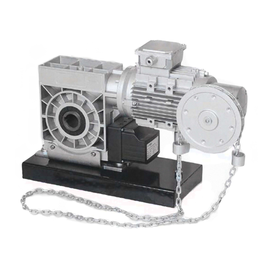
- Page 5 TECHNICAL CHARACTERISTICS KIT COMPONENTS The KVM2020 is a motor developed for industrial door applications that require anti fall equipment. In the kit you will find these components: The safety brake is built into the gear and the drive unit is installed directly on the door shaft.
- Page 6 02. AUTOMATION MOTOR AND MANEUVERS BOARD DIMENSIONS • Motor dimensions (a x b x c) 622x270x166 • Reducer width (c) • Total height of the motor (a) • Motor Depth (b) • Eletronic Board’s Total Height (a') 104 ~ 172 •...
- Page 7 03. INSTALLATION AUTOMATION INSTALL INSTALLATION WITH TRACTION TO THE SHAFT • Reducer a) Insert the motor through the roller shaft and insert a Right support Roller shaft Roller shaft Motor steel dowel Support plate Left support Roller Washer Manual Support plate chain device Thrust washer Hexagon screws...
- Page 8 03. INSTALLATION 03. INSTALLATION LIMIT-SWITCHES ADJUSTMENT MANEUVERS BOARD FIXATION Security Closing limit-switch Adjusting limit-switch Opening (Opening) screw limit-switch Security limit-switch (Closing) Fixing screw Adjusting screw Fixing screw Limit-switch a) Course adjustment micros b) Limit-switch MARK THE HOLES Make sure the door is open and which is the opening limit switch. Make a mark on the wall at a distance of 1500mm from the ground.
- Page 9 04. TROUBLESHOOTING INSTRUCTIONS FOR FINAL CONSUMERS/SPECIALIZED TECHNICIANS OCCURRENCE POSSIBLE CAUSES RESOLUTION Connect the power supply. Lack of electrical supply. Replace the fuse. Damaged fuse. Check and connect the connection line. The gate does not open in the "ON" state The connection cable may be damaged, loose or dropped. Pull the manual chain slightly to reset the mi- The contact of the manual protection microswitch does not return.
Need help?
Do you have a question about the KVM2020 and is the answer not in the manual?
Questions and answers