Sign In
Upload
Download
Table of Contents
Contents
Add to my manuals
Delete from my manuals
Share
URL of this page:
HTML Link:
Bookmark this page
Add
Manual will be automatically added to "My Manuals"
Print this page
×
Bookmark added
×
Added to my manuals
Manuals
Brands
Riello Manuals
Burner
RS 70 E
Installation, use and maintenance instructions
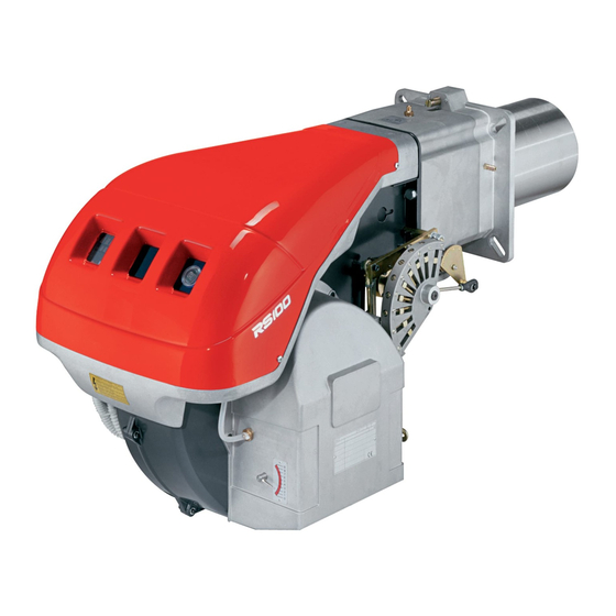
Riello RS 70 E Installation, Use And Maintenance Instructions
Forced draught gas burners
Hide thumbs
1
2
Table Of Contents
3
4
5
6
7
8
9
10
11
12
13
14
15
16
17
18
19
20
21
22
23
24
25
26
27
28
29
30
31
32
33
34
35
36
37
38
39
40
page
of
40
Go
/
40
Contents
Table of Contents
Bookmarks
Table of Contents
Table of Contents
1 Information and General Instructions
Information about the Instruction Manual
Introduction
General Dangers
Safety Precautions
Danger: Live Components
Guarantee and Responsibility
Owner's Responsibility
2 Safety and Prevention
Introduction
Personnel Training
3 Technical Description of the Burner
Technical Data
Electrical Data
Fan Motor IE2/EPACT
3.3 Burner Models Designations
Packaging
Overall Dimensions
Burner Equipment
Firing Rates
Minimum Furnace Dimensions
Procedure to Refer Burner Operating Condition in High Altitude Plants
Burner Components
Control Box for the Air/Fuel Ratio (LMV37.4
Actuators (SQM33.5
4 Installation
Notes on Safety for the Installation
Handling
Preliminary Checks
Operation Position
Securing the Burner to the Boiler
Boring the Boiler Plate
Length of the Blast Tube
Combustion Head Calibration
Electrode and Ignition Pilot Adjustment
Combustion Head Setting
Gas Train Assembly
Gas Feeding Line
Gas Pressure
Electrical Wiring
Electrical Connections
Supply Cables and External Connections Passage
4.14 Thermal Relay Calibration
4.14.1 Electro-Mechanical Thermal Relay
4.14.2 Electronic Thermal Relay
4.15 Motor Connection at 208-230 or 460V
4.16 Motor Connection at 575V
4.17 Reversible Direction
5 Start-Up, Calibration and Operation of the Burner
Notes on Safety for the First Start-Up
Operations before Start-Up
Burner Start-Up
Final Calibration of the Pressure Switches
Air Pressure Switch
Maximum Gas Pressure Switch
Minimum Gas Pressure Switch
Final Checks (with the Burner Working)
6 Maintenance
Notes on Safety for the Maintenance
Maintenance Programme
Maintenance Frequency
Checking and Cleaning
Opening the Burner
Closing the Burner
A Appendix - Spare Parts
B Appendix - Accessories
Appendix - Burner Start up Report
Advertisement
Quick Links
1
Information about the Instruction Manual
2
A Appendix - Spare Parts
Download this manual
Installation, use and maintenance instructions
Forced draught gas burners
Progressive two-stage or modulating operation
20016861
20016862
20016863
Code
Model
RS 70/E
RS 100/E
RS 130/E
20017786 (7) - 05/2012
Table of
Contents
Previous
Page
Next
Page
1
2
3
4
5
Advertisement
Table of Contents
Need help?
Do you have a question about the RS 70 E and is the answer not in the manual?
Ask a question
Questions and answers
Related Manuals for Riello RS 70 E
Burner Riello RS 100 Installation, Use And Maintenance Instructions
Forced draught gas burners (21 pages)
Burner Riello RS 70 Installation, Use And Maintenance Instructions
Lpg kit (25 pages)
Burner Riello RS 70 Installation, Use And Maintenance Instructions
Forced draught gas burners (52 pages)
Burner Riello RS 70 Installation, Use And Maintenance Instructions
Forced draught gas burners (72 pages)
Burner Riello RS 70/M Installation, Use And Maintenance Instructions
Long head kit (9 pages)
Burner Riello RS 70/M Installation, Use And Maintenance Instructions
Forced draught gas burners (52 pages)
Burner Riello RS 100/M Installation, Use And Maintenance Instructions
Forced draught gas burners (56 pages)
Burner Riello RS 70/E MZ Installation, Use And Maintenance Instructions
Blown type gas burners (56 pages)
Burner Riello RS 70/E Installation, Use And Maintenance Instructions
Forced draught gas burners, progressive two-stage or modulating operation (76 pages)
Burner Riello C9324400 Installation, Use And Maintenance Instructions
Forced draught gas burners (40 pages)
Burner Riello RS 70 VA Installation, Use And Maintenance Instructions
Burners in air duct, progressive two-stage or modulating operation (40 pages)
Burner Riello RS 70 VA Installation, Use And Maintenance Instructions
Burners in air duct, progressive two-stage or modulating operation (64 pages)
Burner Riello RS 70/EV Installation, Use And Maintenance Instructions
Forced draught gas burners (44 pages)
Burner Riello RS Series Installation, Use And Maintenance Instructions
Forced draught gas burners (72 pages)
Burner Riello RS 300/EV BLU Installation, Use And Maintenance Instructions
Forced draught gas burners (48 pages)
Burner Riello RS 45 BLU Installation, Use And Maintenance Instructions
Forced draught gas burner (44 pages)
This manual is also suitable for:
Rs 100 e
Rs 130 e
20016861
20016862
20016863
Table of Contents
Print
Rename the bookmark
Delete bookmark?
Delete from my manuals?
Login
Sign In
OR
Sign in with Facebook
Sign in with Google
Upload manual
Upload from disk
Upload from URL


Need help?
Do you have a question about the RS 70 E and is the answer not in the manual?
Questions and answers