Table of Contents
Advertisement
Advertisement
Table of Contents

Related Manuals for Riello RS 300/EV BLU


Summary of Contents for Riello RS 300/EV BLU
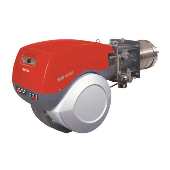
- Page 1 Installation, use and maintenance instructions Forced draught gas burners Modulating operation CODE MODEL TYPE 20116478 RS 300/EV BLU 849T2 20116480 RS 400/EV BLU 850T2 20116483 RS 500/EV BLU 856T2 20116487 RS 650/EV BLU 1123T2 20116494 RS 800/EV BLU 887T2 20123768 (2) - 01/2017...
- Page 2 Translation of the original instructions...
-
Page 3: Table Of Contents
Contents Declarations....................................3 Information and general warnings............................4 Information about the instruction manual ........................4 2.1.1 Introduction.................................. 4 2.1.2 General dangers................................4 2.1.3 Other symbols ................................4 2.1.4 Delivery of the system and the instruction manual...................... 5 Guarantee and responsibility............................5 Safety and prevention................................ - Page 4 Contents Burner ignition ................................26 Combustion air adjustment ............................27 6.5.1 Air adjustment for maximum output ...........................27 6.5.2 Air/fuel adjustment and output modulation system ....................27 Pressure switch adjustment ............................28 6.6.1 Air pressure switch - check CO..........................28 6.6.2 Maximum gas pressure switch...........................28 6.6.3 Minimum gas pressure switch............................28 6.6.4 PVP pressure switch kit .............................28...
-
Page 5: Declarations
The quality is guaranteed by a quality and management system certified in accordance with ISO 9001:2015. Manufacturer's Declaration RIELLO S.p.A. declares that the following products comply with the NOx emission limits specified by German standard “1. BImSchV revision 26.01.2010”. Product... -
Page 6: Information And General Warnings
Information and general warnings Information and general warnings Information about the instruction manual 2.1.1 Introduction WARNING: MOVING PARTS The instruction manual supplied with the burner: This symbol indicates that you must keep limbs is an integral and essential part of the product and must not away from moving mechanical parts;... -
Page 7: Delivery Of The System And The Instruction Manual
Information and general warnings The system supplier must carefully inform the user about: 2.1.4 Delivery of the system and the instruction – the use of the system; manual – any further tests that may be required before activating the When the system is delivered, it is important that: system;... -
Page 8: Safety And Prevention
Safety and prevention Safety and prevention Introduction The burners have been designed and built in compliance with the type and pressure of the fuel, the voltage and frequency of the current regulations and directives, applying the known technical electrical power supply, the minimum and maximum deliveries for rules of safety and envisaging all the potential danger situations. -
Page 9: Technical Description Of The Burner
230V / 50-60Hz 110/50/60 110V / 50-60Hz 3/400/50 230/50/60 BASIC DESIGNATION EXTENDED DESIGNATION Models available Designation Voltage Start-up Code RS 300/EV BLU FS2 3/230-400/50 Direct/Inverter 20116478 RS 400/EV BLU FS2 3/400/50 Direct/Inverter 20116480 RS 500/EV BLU FS2 3/400/50 Direct/Inverter 20116483... -
Page 10: Technical Data
Technical description of the burner Technical data Model RS 300/EV BLU RS 400/EV BLU RS 500/EV BLU RS 650/EV BLU RS 800/EV BLU Type 849 T2 850 T2 856 T2 1123 T2 887 T2 Power 500/1350 ÷ 3800 800/1840÷4550 1000/2500÷5170 1410/3020÷6500 1200/3500÷8100... -
Page 11: Burner Categories - Countries Of Destination
Bear in mind that inspection of the combustion head requires the burner to be opened and the rear part turned on the hinge. The l position is reference for the refractory thickness of the boiler door. D3099 Fig. 1 RS 300/EV BLU 1325 DN65 1175 1055 RS 400/EV BLU... -
Page 12: Firing Rates
1,013 mbar (approx. 0 m limit of the diagram: WARNING a.s.l.), and with the combustion head adjusted as shown on pag. 21. Model RS 300/EV BLU RS 400/EV BLU RS 500/EV BLU 1000 RS 650/EV BLU 1400... -
Page 13: Test Boiler
Technical description of the burner Test boiler The burner/boiler combination does not pose any problems if the The firing rates were set in relation to special test boilers, accord- boiler is EC approved and its combustion chamber dimensions ing to EN 676 regulations. are similar to those indicated in the diagram (Fig. -
Page 14: Burner Description
Technical description of the burner 4.10 Burner description 20071047 Fig. 4 Lifting rings 17 Air damper movement gears Impeller 18 Air pressure switch Fan motor 19 Combustion head air pressure test point Air damper servomotor 20 Maximum gas pressure switch with pressure test point Combustion head gas pressure test point 21 Flame sensor Combustion head... -
Page 15: Electrical Panel Description
Technical description of the burner 4.11 Electrical panel description D9780 Fig. 5 Clean contact relay Calibration device with electronic cam Ignition transformer Stop push-button Off-automatic selector Warning lamp for voltage of auxiliaries Fan motor lock-out warning lamp Light signalling burner lockout Remote type control panel 10 Auxiliary terminal board 11 Main terminal supply board and Inverter kit... -
Page 16: Air/Fuel Ratio Control Apparatus (Etamatic Oem)
To avoid accidents, material or environmental damage, observe the following instructions! The control box is a safety device! Avoid opening WARNING or modifying it, or forcing its operation. Riello S.p.A. cannot assume any responsibility for dam- age resulting from unauthorised interventions! Risk of explosion! - Page 17 Technical description of the burner Mechanical structure Installation notes – Check the electric wiring inside the boiler complies with the – The control box manages up to 4 adjustment components national and local safety regulations. based on a command variable, according to freely program- –...
-
Page 18: 4.13 Display
Technical description of the burner 4.13 Display Technical data Meaning of the buttons Electrical 24V DC Reset Max. output consumption Load / fault report up Customer interface (Fig. 8) Load / fault report down Manual On / Off mode Display switching –... -
Page 19: Servomotors
Technical description of the burner 4.15 Servomotors Warnings To avoid accidents, material or environmental damage, observe the following instructions! Avoid opening, modifying or forcing the actuators. WARNING All interventions (assembly and installation operations, assistance, etc.) must be carried out by qualified personnel. ... -
Page 20: Installation
Installation Installation Notes on safety for the installation After carefully cleaning all around the area where the burner is to The installation of the burner must be carried out be installed, and arranging for the environment to be illuminated by qualified personnel, as indicated in this manual correctly, proceed with the installation operations. -
Page 21: Operating Position
For boilers with front flue passes 1)(Fig. 16) or flame inversion chamber, a protection in refractory material 5) must be inserted between the boiler fettling 2) and the blast tube 4). RS 300/EV BLU RS 400/EV BLU This protective fettling must not compromise the extraction of the blast tube. -
Page 22: Securing The Burner To The Boiler
Installation Securing the burner to the boiler Prepare a suitable lifting system using the rings 3)(Fig. 16), after removing the fixing screws 7) of the casing 8). Fit the heat insulation supplied onto the blast tube (4)(Fig. 16). Fit the entire burner onto the boiler hole prepared previously (Fig. -
Page 23: Combustion Head Adjustment
Installation 5.10 Combustion head adjustment The air damper servomotor 4)(Fig. 4 on pag. 12), beyond varying the air output according to the output demand, through a leverage varies the combustion head adjustment. In the factory, the hole is adjusted for the minimum stroke (hole Varying the tie-rod position on the holes 2) and 3) (Fig. -
Page 24: Gas Feeding
Installation 5.11 Gas feeding Explosion danger due to fuel leaks in the pres- MBC “threaded” ence of a flammable source. Precautions: avoid knocking, attrition, sparks and heat. Make sure the fuel interception tap is closed be- fore performing any operation on the burner. The fuel supply line must be installed by qualified personnel, in compliance with current standards and laws. -
Page 25: 5.11.2 Gas Train
Installation 5.11.2 Gas train Approved according to standard EN 676 and provided separately Pay attention when handling the train: danger of from the burner. crushing of limbs. To select the correct gas train model, refer to the supplied "Burn- er-gas train combination" manual. Make sure that the gas train is properly installed by checking for any fuel leaks. -
Page 26: Gas Pressure
Installation 5.11.4 Gas pressure 1 p (mbar) 2 p (mbar) G 20 G 25 G 20 G 25 The Tab. I indicates the pressure drop of the combustion head 1245 11.6 and the gas butterfly valve depending on the operating output of 1500 13.9 the burner. -
Page 27: Electrical Wiring
Installation 5.12 Electrical wiring Notes on safety for the electrical wiring The electrical wiring must be carried out with the electrical supply disconnected. Electrical wiring must be made in accordance with the regulations currently in force in the country of destination and by qualified personnel. -
Page 28: Start-Up, Calibration And Operation Of The Burner
Start-up, calibration and operation of the burner Start-up, calibration and operation of the burner Notes on safety for the first start-up The first start-up of the burner must be carried out Check the correct working of the adjustment, com- by qualified personnel, as indicated in this manual mand and safety devices. -
Page 29: Combustion Air Adjustment
Start-up, calibration and operation of the burner Combustion air adjustment 6.5.2 Air/fuel adjustment and output modulation Fuel/combustion air synchronisation is done with the relevant servomotors (air and gas) by logging a calibration curve by system means of the electronic cam. The air/gas regulator and output modulation system equipping It is advisable, to reduce the loss and for a wide calibration field, RS/EV series burners performs a number of integrated functions... -
Page 30: Pressure Switch Adjustment
Start-up, calibration and operation of the burner Pressure switch adjustment 6.6.1 Air pressure switch - check CO Adjust the air pressure switch (Fig. 31) after performing all other burner adjustments with the air pressure switch set to the start of the scale. -
Page 31: Maintenance
Maintenance Maintenance Notes on safety for the maintenance The periodic maintenance is essential for the good operation, safety, yield and duration of the burner. Disconnect the electrical supply from the burner It allows you to reduce consumption and polluting emissions and by means of the main system switch. -
Page 32: Safety Components
Maintenance Combustion Safety component Life cycle If the combustion values measured before starting maintenance 10 years or 250.000 do not comply with applicable legislation or do not indicate effi- Flame control cient combustion, consult the Tab. K or contact our Technical operation cycles Support Service to implement the necessary adjustments. -
Page 33: Faults - Possible Causes - Solutions
Faults - Possible causes - Solutions Faults - Possible causes - Solutions If faults arise in ignition or operations, the burner performs a "safety stop", which is signalled by the red burner lockout LED. The display visualises alternately the lockout code and the rela- tive diagnostic. -
Page 34: Appendix - Accessories
521 - 357 671 - 507 20028449 For (B) - (I) positions, refer to paragraph “Maximum dimensions”. Inverterkit (VSD) Burner Max. output (kW) Code RS 300/EV BLU 20081675 RS 400/EV BLU 20081645 RS 500/EV BLU 20081646 RS 650/EV BLU 18.5... - Page 35 Appendix - Accessories LPG kit Burner Code RS 300/EV BLU 3010445 RS 400-500/EV BLU 20012916 RS 800/EV BLU 20007822 Spacer kit Burner Code All models 20008903 Gas trains in compliance with EN 676 Please refer to manual. 20123768...
-
Page 36: Appendix - Electrical Panel Layout
Appendix - Electrical panel layout Appendix - Electrical panel layout Index of layouts Indication of references Single-wire output layout Functional diagram Functional diagram Functional diagram Functional diagram Electrical wiring that the installer is responsible for Electrical wiring that the installer is responsible for Indication of references / 1 . - Page 37 Appendix - Electrical panel layout 20123768...
- Page 38 Appendix - Electrical panel layout 20123768...
- Page 39 Appendix - Electrical panel layout 20123768...
- Page 40 Appendix - Electrical panel layout 20123768...
- Page 41 Appendix - Electrical panel layout 20123768...
- Page 42 Appendix - Electrical panel layout 20123768...
- Page 43 Appendix - Electrical panel layout 20123768...
- Page 44 Appendix - Electrical panel layout Wiring layout key Display and calibration unit Electronic cam Flame sensor module Filter Pressure probe Pressure probe Auxiliary fuse Pt100 3 wire probe 3 wire probe Inverter Rpm sensor (with Inverter kit only) sensor Light signalling of mains live state Fan motor lock-out warning lamp Lock-out warning lamp Clean contacts output relay burner switched on...
- Page 48 RIELLO S.p.A. I-37045 Legnago (VR) Tel.: +39.0442.630111 http:// www.riello.it http:// www.riello.com Subject to modifications...
Need help?
Do you have a question about the RS 300/EV BLU and is the answer not in the manual?
Questions and answers