Table of Contents
Advertisement
Quick Links
Advertisement
Table of Contents

Subscribe to Our Youtube Channel
Related Manuals for SMC Networks IL201 Series


Summary of Contents for SMC Networks IL201 Series
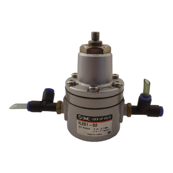
- Page 1 No.IL02-OM00011-B PRODUCT NAME LOCK UP VALVE MODEL/ Series IL201 IL211...
-
Page 2: Table Of Contents
Table of Contents Instructions for your Safety 1. Summary 2. Specification 3. Operation Principle 4. Transportation and Storage 5. Mounting and Piping 6. Precautions in Using 7. Maintenance 8. Troubleshooting 9. Spare Parts List 10. Drawing 10 11... - Page 3 Safety Instructions These safety instructions are intended to prevent hazardous situations and/or equipment damage. These instructions indicate the level of potential hazard with the labels of “Caution,” “Warning” or “Danger.” They are all important notes for safety and must be followed in addition to International Standards (ISO/IEC) , and other safety regulations.
-
Page 4: Instructions For Your Safety 1
Safety Instructions Caution The product is provided for use in manufacturing industries. The product herein described is basically provided for peaceful use in manufacturing industries. If considering using the product in other industries, consult SMC beforehand and exchange specifications or a contract if necessary. If anything is unclear, contact your nearest sales branch. -
Page 5: Summary
1. Summary When accidents of air source and piping in pneumatic process control line cause supplying air failure such as dropping setting pressure, lock-up valve shuts pneumatic circuit between air source and operating part. 2. Specification Signal pressure Max. 1MPa (Note 1) Setting pressure range 0.14 0.7MPa (Note 1) Line pressure... -
Page 7: Transportation And Storage
4. Transportation and Storage Warning (1) Handle the product with care. (2) Do not expose to rain. (3) The product is packed in a vinyl bag for shipment to prevent from dust. Avoid taking out of the bag just before piping even after unpacking. (4) If the product is kept unpacking for a certain period, select a place where there is no moisture nor corrosive gas. -
Page 8: Precautions In Using
6. Precautions in using Warning Operation (1) Do not operate the lock-up valve out of the specifications, because it causes malfunction. (2) If lock-up valve failure affecting the system is expected, provide a safety circuit for the system to avoid danger. (3) When supplying air pressure fails and it decreases lower than the setting pressure, air source and operating part are shut down, but since the pressure decrease gradually, check line pressure (movement of actuator) constantly. -
Page 9: Maintenance
7. Maintenance Warning (1) If handled improperly, compressed air can be dangerous. Maintenance and replacement of unit parts should be performed only by trained and experienced personnel for instrumentation equipment as well as following the product specifications. (2) For maintenance, removing lock-up valve or replacing unit parts without dismounting, stop supply pressure and exhaust residual pressure beforehand. -
Page 10: Troubleshooting
8. Troubleshooting Warning Stop using the product if failures are not improved. Failures Causes Countermeasures Disassembling cleaning Dust and carbon adhere to (Change diaphragm Ass’y if there seating part of exhaust port of is a flaw on seating part of Excess flow from exhaust diaphragm Ass’y. -
Page 11: Spare Parts List
9. Spare Parts List IL201 Part number Part name Material Quantity 29030 1 Diaphragm Ass’y 29038 Diaphragm 290311#1 Valve BRASS JIS B 2401, P21 “O” ring JIS B 2401, P8 “O” ring JIS B 2401, P5 “O” ring JIS B 2401, P3 “O”... - Page 12 -10- -10-...
-
Page 13: Drawing 10
-11- -11- -11-... - Page 14 Revision A Format change and content review B Drawings update 4-14-1, Sotokanda, Chiyoda-ku, Tokyo 101-0021 JAPAN Tel: + 81 3 5207 8249 Fax: +81 3 5298 5362 http://www.smcworld.com Note: Specifications are subject to change without prior notice and any obligation on the part of the manufacturer. ©...
Need help?
Do you have a question about the IL201 Series and is the answer not in the manual?
Questions and answers