Advertisement
Quick Links
Installation
IMPORTANT:
Use this M9106-xGx-2 Series
actuator only as an operating control. Where failure
or malfunction of the this M9106-xGx-2 actuator
could lead to personal injury or property damage to
the controlled equipment or other property,
additional precautions must be designed into the
control system. Incorporate and maintain other
devices, such as supervisory or alarm systems or
safety or limit controls, intended to warn of or protect
against failure or malfunction of the M9106-xGx-2
Series actuator.
Utiliser ce M9106-xGx-2 Series actuator uniquement
en tant que dispositif de contrôle de fonctionnement.
Lorsqu'une défaillance ou un dysfonctionnement du
M9106-xGx-2 actuator risque de provoquer des
blessures ou d'endommager l'équipement contrôlé
ou un autre équipement, la conception du système
de contrôle doit intégrer des dispositifs de protection
supplémentaires. Veiller dans ce cas à intégrer de
façon permanente d'autres dispositifs, tels que des
systèmes de supervision ou d'alarme, ou des
dispositifs de sécurité ou de limitation, ayant une
fonction d'avertissement ou de protection en cas de
défaillance ou de dysfonctionnement du
M9106-xGx-2 Series actuator.
Parts Included
•
M9106-xGx-2 actuator
•
M9000-160 anti-rotation bracket
•
two No. 12-24 x 1/2 in. self-tapping hex
washer-head screws
•
spade terminals
Special Tools Needed
•
drill with a 3/16 in. (No. 15, 4.57 mm) drill bit
•
5/16 in. (8 mm) square socket or 3/8 in.(10 mm)
12-point socket
•
wire/terminal crimper
© 2014 Johnson Controls, Inc.
Part No. 34-636-1085, Rev. D
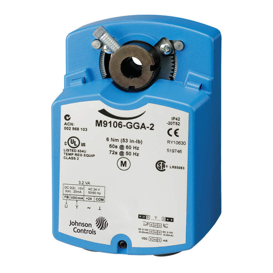
M9106-xGx-2 Series Electric
Non-Spring Return Actuators
Installation Instructions
Issue Date
Mounting
The actuators are not position sensitive, and may be
mounted in any convenient orientation. They may be
installed on a 3/8 to 1/2 in. (10 to 12.7 mm) round shaft
or a 3/8 in. (10 mm) square shaft, 1.7 in. (43 mm) or
longer. If the shaft is less than 1.7 in. (43 mm), install
an extension recommended by the damper
manufacturer.
To mount the actuator, proceed as follows:
1. Press and hold the gear release lever, and rotate
the coupler to the 0 or 90° position. Release the
gear release lever. (See Figure 1.)
Damper
Frame
or Duct
Coupler
Set Screw
Coupler
Gear
Release
Note:
"A" is the distance from the center of the holes in
the anti-rotation bracket to the center of the shaft.
(See Table 1.)
Figure 1: Mounting Positions
Table 1: Distances from the Anti-rotation
Bracket to the Shaft Center
Shaft Diameter
"A" Dimensions
5-1/8 in.
(See Figure 1.)
130 mm
M9106-xGx-2
June 30, 2014
Shaft
Center
A
Anti-rotation
Bracket
1/2 in.
3/8 in.
5-1/16 in.
128 mm
www.johnsoncontrols.com
1
Advertisement

Related Manuals for Johnson Controls M9106 Series


Summary of Contents for Johnson Controls M9106 Series
- Page 1 3/16 in. (No. 15, 4.57 mm) drill bit (See Figure 1.) 130 mm 128 mm • 5/16 in. (8 mm) square socket or 3/8 in.(10 mm) 12-point socket • wire/terminal crimper © 2014 Johnson Controls, Inc. Part No. 34-636-1085, Rev. D www.johnsoncontrols.com...
- Page 2 Figure 4. Note: When installing the actuator to a Johnson Controls damper, use the existing holes in Damper the damper frame. Damper 7. Attach the anti-rotation bracket to the damper...
-
Page 3: Setup And Adjustments
Less than 90 Degrees If the damper shaft rotation is less than 90°, the IMPORTANT: Do not remove the end-stop rotation range of the actuator has to be adjusted with set screws, as this could interfere with the actuator’s the scale on the actuator cover. (See Figure 5.) operation. - Page 4 GGx Models The M9106-GGx-2 proportional actuators are factory set for Direct Acting (DA) mode with Jumper W1 in the DA position. Remove Jumper W1 Mode and place it in the RA position. (See Figure 7.) Time Switch Settings (Minutes) Jumper W1 Direct Acting (DA) Board 1 Reverse Acting (RA)
- Page 5 Wiring Note: To avoid excessive wear or drive time on the motor for the AGx models, use a controller and/or CAUTION: Risk of Property Damage. software that provides a time-out function to remove Do not apply power to the system before checking the signal at the end of rotation (stall).
-
Page 6: Repairs And Replacement
Auxiliary Switches (xGC Models) Switch S2 The M9106-xGC-2 models have two built-in To change the angle of Switch S2 to 70°, refer to auxiliary switches that may be set for any angle Figure 13 and proceed as follows: between 0 and 90° (factory set for 10 and 80°, 1. -
Page 7: Technical Data
The performance specifications are nominal and conform to acceptable industry standards. For application at conditions beyond these specifications, consult the local Johnson Controls office. Johnson Controls, Inc. shall not be liable for damages resulting from misapplication or misuse of its products. - Page 8 507 E. Michigan Street, Milwaukee, WI 53202 Metasys® and Johnson Controls® are registered trademarks of Johnson Controls, Inc. All other marks herein are the marks of their respective owners. © 2014 Johnson Controls, Inc. M9106-xGx-2 Series Electric Non-Spring Return Actuators Installation Instructions...
Need help?
Do you have a question about the M9106 Series and is the answer not in the manual?
Questions and answers