Table of Contents
Advertisement
Quick Links
Advertisement
Table of Contents

Related Manuals for Newland EM2039 Series


Summary of Contents for Newland EM2039 Series
- Page 1 EM2039 Series OEM Scan Engine Integration Guide...
- Page 2 Please read through the manual carefully before using the product and operate it according to the manual. It is advised that you should keep this manual for future reference. Do not disassemble the device or remove the seal label from the device. Otherwise, FuJian Newland Auto-ID Tech. Co., Ltd. does not assume responsibility for the warranty or replacement.
- Page 3 Revision History Version Description Date V1.0.0 Initial release. May 21, 2013...
-
Page 4: Table Of Contents
Table of Contents Chapter 1 Introduction ................................. 1 Product Overview ................................1 Documents ..................................1 Aimer ....................................1 Illumination ..................................2 Chapter 2 Installation ................................... 3 General Requirements ..............................3 ESD ..................................3 Dust and Dirt ................................3 Ambient Environment ............................... 3 Thermal Considerations ............................ - Page 5 Chapter 4 Interfaces ................................... 16 Connections & Pinouts ..............................16 TTL-232 ................................. 17 USB ..................................18 Micro USB ................................18 Host Interface Connectors .............................. 19 12-Pin FPC Connector ............................19 Micro USB Connector ............................20 External Circuits ................................21 Good Read LED Circuit ............................21 Beeper Circuit ................................
-
Page 7: Chapter 1 Introduction
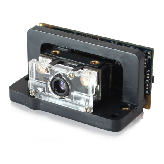
Chapter 1 Introduction Product Overview NLS-EM2039 series embedded 2D barcode scan engines, armed with the Newland patented computerized image recognition system, bring about a new era of 2D barcode scan engines. The EM2039s’ decoder chip ingeniously blends technology and advanced chip design &... -
Page 8: Illumination
Illumination The EM2039 has two red LEDs (wavelength: 625± 10 nm) for supplementary lighting, making it possible to scan barcodes even in complete darkness. The illumination can be programmed On or Off. Since red light is used as illumination and the engine’s lens imaging system is coated with AR film which has obvious anti-reflection effect against red light, the engine shows better reading performance on barcodes printed in non-red colors. -
Page 9: Chapter 2 Installation
Chapter 2 Installation General Requirements ESD protection has been taken into account when designing the EM2039 and the engine is shipped in ESD safe packaging. Always exercise care when handling the engine outside its package. Be sure grounding wrist straps and properly grounded work areas are used. Dust and Dirt The EM2039 must be sufficiently enclosed to prevent dust particles from gathering on the imager and lens. -
Page 10: Installation Orientation
Installation Orientation Fig. 2-1 illustrates a front view of the EM2039 after installation. Fig. 2-1... -
Page 11: Optics
Optics Window Placement The window should be positioned properly to let the illumination and aiming beams pass through as much as possible and no reflections back into the engine (reflections can degrade the reading performance). The window should be mounted close to the front of the engine (parallel). The maximum distance is measured from the front of the engine housing to the farthest surface of the window. -
Page 12: Window Material And Color
Window Material and Color Wavelengths of illumination and aiming beams should be taken into consideration when choosing window material and color, to achieve the possible highest spectral transmission, lowest haze level and homogeneous refractive index. It is suggested to use PMMA or optical glass with spectral transmittance over 90% and haze less than 1%. - Page 13 Illumination & Aiming Fig. 2-3 Fig. 2-4...
-
Page 14: Ambient Light
Fig. 2-5 Fig. 2-6 Ambient Light The EM2039 shows better performance with ambient light. However, high-frequency pulsed light can result in performance degradation. Eye Safety The EM2039 has LEDs that create the aiming and illumination beams. These LEDs are bright, but testing has been done to demonstrate that the engine is safe for its intended application under normal usage conditions. -
Page 15: Mounting
Mounting The EM2039s provide combined type (imager and decoder board assembled on an L-shaped bracket) and discrete type (imager and decoder board separated) to cater for different mounting needs. For the combined type, the user can simply mount the EM2039 on the target device. The combined type is easy for integration and is suitable for devices with enough space inside. - Page 16 Bottom View Fig. 2-8 Top View Fig. 2-9...
-
Page 17: Imager - Discrete Type (Unit: Mm)
Imager - Discrete Type (unit: mm) Front View Fig. 2-10 Bottom View Fig. 2-11 Top View Fig. 2-12... -
Page 18: Decoder Board - Discrete Type (Unit: Mm)
Right View Fig. 2-13 Decoder Board - Discrete Type (unit: mm) Front View Fig. 2-14... - Page 19 Back View Fig. 2-15 Right View Fig. 2-16...
-
Page 20: Chapter 3 Electrical Specifications
Chapter 3 Electrical Specifications Power Supply Do not power up the EM2039 until it is properly connected. Be sure the power is cut off before connecting a flexible cable to or disconnecting a flexible cable from the host interface connector. This could damage the engine. -
Page 21: Dc Characteristics
DC Characteristics Operating Voltage T=23° C Parameter Minimum Typical Maximum Unit Operating Voltage Current (@3.3V) Idle Low power I/O Requirements VDD=3.3V, VSS=0V, T=23° C Parameter Minimum Maximum Unit -0.3 0.2*VDD 0.7*VDD VDD+0.3 VDD-0.4... -
Page 22: Chapter 4 Interfaces
Chapter 4 Interfaces Connections & Pinouts The EM2039 is equipped with 12-pin FPC connector and Micro USB connector. 12-pin FPC connector can be used as TTL-232 interface or USB interface. Micro USB connector can only be used as standard USB interface. Fig. -
Page 23: Ttl-232
TTL-232 The table below describes the pin functions of FPC connector used as TTL-232 interface. PIN# Signal Name Function 232INV Output: High = TTL-232 interface; Low = USB interface Power: supply voltage input Ground: power and signal ground Input: TTL level RS-232 receive data Output: TTL level RS-232 transmit data nCTS Input: TTL level RS-232 clear to send... -
Page 24: Usb
The table below describes the pin functions of FPC connector used as USB interface. PIN# Signal Name Function 232INV Output: High = TTL-232 interface; Low = USB interface Power: supply voltage input Ground: power and signal ground Input/Output: USB D- signal Reserved Pin function reserved Input/Output: USB D+ signal... -
Page 25: Host Interface Connectors
Host Interface Connectors The EM2039 is equipped with 12-pin FPC connector and Micro USB connector. 12-Pin FPC Connector The EM2039 uses an FFC/FPC connector (CF20121V0R0-LF) manufactured by CviLux. Fig. 4-2... -
Page 26: Micro Usb Connector
Micro USB Connector The EM2039’s Micro USB connector is a standard connector and can be used accordingly. Fig. 4-3... -
Page 27: External Circuits
External Circuits Good Read LED Circuit The circuit below is used to drive an external LED for indicating good read. The left part shows internal Good Read LED driver circuit on the decoder board and the right part shows external circuit that users may utilize in actual application. -
Page 28: Sleep Mode Led Circuit
Sleep Mode LED Circuit The circuit below is used to drive an external LED for indicating that the engine is in sleep mode. The left part shows internal Sleep Mode LED driver circuit on the decoder board and the right part shows external circuit that users may utilize in actual application. -
Page 29: Wake-Up Circuit
Wake-Up Circuit The circuit below is used to wake the engine from sleep mode. The right part shows internal driver circuit on the decoder board and the left part shows external circuit that users may utilize in actual application. The nWAKE signal is from Pin 11 of the 12-pin FPC connector. Users can adjust the external circuit and its function as per actual needs, on condition that the external circuit matches the internal circuit. -
Page 30: Chapter 5 Development Tools
Chapter 5 Development Tools The EM2039’s development tools include both software and hardware and can be utilized for engine performance evaluation, application development and engine configuration. The EVK is provided to help users to test and evaluate the EM2039, which contains beeper & beeper driver circuit, LED &... - Page 31 Newland Ibérica +34 (0) 93 303 74 66 info@newland-id.es Newland France +31 (0) 345 87 00 33 france@newland-id.com Newland Middle East +31 (0) 345 87 00 33 middleeast@newland-id.com Newland South Africa +27 (0) 11 553 8010 info@newland-id.co.za Newland Italy +39 (0) 342 056 2227 italy@newland-id.com...
Need help?
Do you have a question about the EM2039 Series and is the answer not in the manual?
Questions and answers