Table of Contents
Advertisement
Quick Links
Advertisement
Table of Contents

Related Manuals for Supermicro SCDS3A-261B


Summary of Contents for Supermicro SCDS3A-261B
- Page 1 SCDS3A-261B CHASSIS USER’S MANUAL...
- Page 2 Please Note: For the most up-to-date version of this manual, please see our web site at www.supermicro.com. Super Micro Computer, Inc. ("Supermicro") reserves the right to make changes to the product About This Manual described in this manual at any time and without notice.
-
Page 3: Table Of Contents
Preface The first chapter provides a description of the main components included with this Chapter 1 Introduction chassis and describes the main features of the SCDS3A-261B mini-tower chassis. Overview ......................1-1 This chapter also includes contact information. Shipping Lists ....................1-1 Contacting Supermicro .................. - Page 4 SCDS3A-261B Chassis Manual Chapter 4 System Interface Overview ......................4-1 Power Button and LEDs ................. 4-2 Power Button ....................4-2 LEDs ........................ 4-2 Chapter 5 Chassis Setup and Maintenance Overview ......................5-1 Removing Power from the System ..............5-1 Removing the Chassis Cover ................. 5-2 Removing and Installing Hard Drives .............
-
Page 5: Overview
Chapter 1 Introduction Overview Supermicro’s SCDS3A-261B chassis features a unique and highly-optimized de- sign, allowing most configuration of the chassis to be accomplished without tools or screws. The chassis is equipped with high-efficiency power supply and a high- performance fan provides optimized cooling for the system. Three internal drive bays and four external drive bays offer maximum storage capacity. -
Page 6: Contacting Supermicro
Website: www.supermicro.com Whenever possible, repack the chassis in the original Supermicro carton, using the original packaging material. If these are no longer available, be sure to pack the Europe chassis securely, using packaging material to surround the chassis so that it does Address: Super Micro Computer B.V. - Page 7 SCDS3A-261B Chassis Manual Notes...
-
Page 8: Chapter 2 Standardized Warning Statements For Ac Systems
The following statements are industry standard warnings, provided to warn the user of situations which have the potential for bodily injury. Should you have questions or experience difficulty, contact Supermicro's Technical Support department for assistance. Only certified technicians should attempt to install or configure components. - Page 9 SCDS3A-261B Chassis Manual Warning Statements for AC Systems Warnung جسذٌة اصابة ًتتسبب ف حالة ٌوكي أى ًاًك ف خطز ًٌٌع هذا الزهز !تحذٌز WICHTIGE SICHERHEITSHINWEISE الذوائز بالوخاطز الٌاجوة عي ي على علن ، ك هعذات تعول على أي قبل أى...
-
Page 10: Installation Instructions
SCDS3A-261B Chassis Manual Chapter 2: Warning Statements for AC Systems Installation Instructions Circuit Breaker Warning! Warning! This product relies on the building's installation for short-circuit (overcurrent) Read the installation instructions before connecting the system to the power source. protection. Ensure that the protective device is rated not greater than: 250 V, 20 A. -
Page 11: Power Disconnection Warning
SCDS3A-261B Chassis Manual Chapter 2: Warning Statements for AC Systems ¡Advertencia! 경고! El sistema debe ser disconnected de todas las fuentes de energía y del cable 이 제품은 전원의 단락(과전류)방지에 대해서 전적으로 건물의 관련 설비에 eléctrico quitado de los módulos de fuente de alimentación antes de tener acceso 의존합니다. -
Page 12: Equipment Installation
SCDS3A-261B Chassis Manual Chapter 2: Warning Statements for AC Systems Equipment Installation Waarschuwing Deze apparatuur mag alleen worden geïnstalleerd, vervangen of hersteld door Warning! geschoold en gekwalificeerd personeel. Only trained and qualified personnel should be allowed to install, replace, or service Restricted Area this equipment. -
Page 13: Battery Handling
SCDS3A-261B Chassis Manual Chapter 2: Warning Statements for AC Systems Warnung אזור עם גישה מוגבלת Bei Einsetzen einer falschen Batterie besteht Explosionsgefahr. Ersetzen Sie die Batterie nur durch den gleichen oder vom Hersteller empfohlenen Batterietyp. !אזהרה Entsorgen Sie die benutzten Batterien nach den Anweisungen des Herstellers. -
Page 14: Redundant Power Supplies
SCDS3A-261B Chassis Manual Chapter 2: Warning Statements for AC Systems Redundant Power Supplies امداد الطاقة بوحدات عدة اتصاالت جهاز ال يكون لهذا قد الكهرباء عن وحدة ال لعسل كافة االتصاالت يجب إزالة 경고! Warning! This unit might have more than one power supply connection. All connections must 이... -
Page 15: Comply With Local And National Electrical Codes
SCDS3A-261B Chassis Manual Chapter 2: Warning Statements for AC Systems Attention מתח בפנל האחורי L'équipement doit être installé conformément aux normes électriques nationales et locales. !הרה אז קיימת סכנת מתח בפנל האחורי בזמן תפעול המערכת. יש להיזהר במהלך תיאום חוקי החשמל הארצי... -
Page 16: Hot Swap Fan Warning
SCDS3A-261B Chassis Manual Chapter 2: Warning Statements for AC Systems Warnung Attention Gefährlich Bewegende Teile. Von den bewegenden Lüfterblätter fern halten. La mise au rebut ou le recyclage de ce produit sont généralement soumis à des Die Lüfter drehen sich u. U. noch, wenn die Lüfterbaugruppe aus dem Chassis lois et/ou directives de respect de l'environnement. - Page 17 UL ou CSA câbles certifiés qui ont UL ou CSA indiqué sur le code power cables and AC adaptors. Using any other cables and adaptors could cause pour tous les autres appareils électriques que les produits désignés par Supermicro a malfunction or a fire. Electrical Appliance and Material Safety Law prohibits the seulement.
- Page 18 SCDS3A-261B Chassis Manual Notes 2-20...
-
Page 19: Chapter 3 Chassis Components
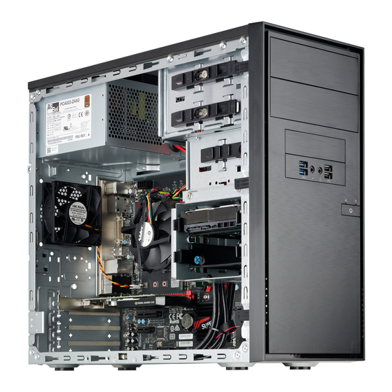
Chapter 3: Chassis Components Chapter 3 Chassis Components This chapter describes some common components included with your chassis. For the latest information and shipping lists, visit: http://www.supermicro.com. Components Drive Bays The chassis supports all of the below: • Three 3.5" SAS/SATA internal drive bays. Hard drives must be purchased separately. -
Page 20: Pci Slots
Infrequently, you may need replacement parts for your system. To ensure the highest level of professional service and technical support, we recommend purchasing ex- clusively from our Supermicro Authorized Distributors/System Integrators/Resellers. A list of Supermicro Authorized Distributors/System Integrators/Resellers can be found at: www.supermicro.com. Click the Where to Buy link. -
Page 21: Chapter 4 System Interface
Chapter 4 System Interface Chapter 4 System Interface Overview The chassis includes a control panel on the front that includes a power button and status monitoring lights, which are described in this chapter. Peripheral Drive Bays Audio LEDs Power Figure 4-1. Chassis Front Bezel... -
Page 22: Power Button And Leds
SCDS3A-261B Chassis Manual Power Button and LEDs Power Button Power: The main power switch is used to apply or remove power from the power supply to the server system. Turning off system power with this button removes the main power but keeps standby power supplied to the system. Therefore, you must unplug system before performing most maintenance tasks. -
Page 23: Chapter 5 Chassis Setup And Maintenance
Overview This chapter covers the steps required to install components and perform mainte- nance on the chassis. Most components of the SCDS3A-261B do not require tools or screws to set them up. Those components which must be secured with screws require only a Phillips screwdriver. -
Page 24: Removing The Chassis Cover
SCDS3A-261B Chassis Manual Chapter 5: Chassis Setup and Maintenance Removing the Chassis Cover Removing and Installing Hard Drives Release Release Figure 5-2. Removing the Hard Drive Carrier from the Chassis Figure 5-1. Removing the Chassis Cover Removing the Chassis Cover Removing and Installing Hard Drives 1. - Page 25 SCDS3A-261B Chassis Manual Chapter 5: Chassis Setup and Maintenance Figure 5-3. Removing the Hard Drive from the Hard Drive Carrier Figure 5-4. Installing the Hard Drive Carrier into the Hard Drive Bay 5. If a hard drive or dummy drive is present, simultaneiously pull both sides of the hard drive carrier open and lift the drive out.
-
Page 26: Installing The I/O Shield And Motherboard
An I/O shield holds the motherboard ports in place. Install the I/O shield before you 7. Connect the cables between the motherboard and the front panel. If using a install the motherboard. board other than one provided by Supermicro it will be necessary to purchase adapter MCP-220-73202-0N. Visit the Supermicro website at http://www. -
Page 27: Removing And Installing The Front Bezel
Removing and Installing the Front Bezel Installing a Peripheral Device Front Bezel Removal The SCDS3A-261B chassis has two bays for optional peripheral devices, such as a DVD drive. 1. Power down the system and remove the power cord from the rear of the... -
Page 28: Installing Expansion Cards
4. Replace the front bezel on the chassis as described in Section 5-6. 5. Slide the peripheral device through the opening in the front bezel into the The SCDS3A-261B chassis includes four slots for expansion cards. The number of chassis bay. -
Page 29: Installing The System Fan
Chapter 5: Chassis Setup and Maintenance Installing the System Fan 5-10 Power Supply The SCDS3A-261B chassis includes a 260 Watt power supply. In the unlikely event that it becomes necessary to replace the power supply, follow the instructions below. Power Supply Figure 5-11. - Page 30 SCDS3A-261B Chassis Manual Notes 5-14...
-
Page 31: Appendix A Power Supply Specifications
Appendix A: Power Supply Specifications Appendix A Power Supply Specifications This appendix lists power supply specifications for your chassis system. The SCDS3A-261B chassis includes a power supply rated at 80 Plus Bronze Level. Operating temperature: 0-50 degrees C. SCDS3A-261B 260W... - Page 32 SCDS3A-261B Chassis Manual Disclaimer (cont.) The products sold by Supermicro are not intended for and will not be used in life sup- port systems, medical equipment, nuclear facilities or systems, aircraft, aircraft devices, aircraft/emergency communication devices or other critical systems whose failure to per- form be reasonably expected to result in significant injury or loss of life or catastrophic property damage.
Need help?
Do you have a question about the SCDS3A-261B and is the answer not in the manual?
Questions and answers