Table of Contents
Advertisement
Quick Links
Advertisement
Table of Contents

Related Manuals for Supermicro SCLA25


Summary of Contents for Supermicro SCLA25
- Page 1 SCLA25 Chassis USER’S MANUAL Revision 1.0...
- Page 2 State of California, USA. The State of California, County of Santa Clara shall be the exclusive venue for the resolution of any such disputes. Supermicro's total liability for all claims will not exceed the price paid for the hardware product.
- Page 3 Installation and maintenance should be performed by experienced technicians only. Please refer to the SCLA25 server specifications page on our website for updates on supported memory, processors and operating systems (http://www.supermicro.com).
-
Page 4: Table Of Contents
Supermicro SCLA25 Chassis User's Manual Contents Chapter 1 Introduction 1.1 Overview ..........................7 1.2 Unpacking the System ......................7 1.3 Chassis Features .........................8 Control Panel ........................8 Front Features ........................9 Rear Features ........................9 Chapter 2 Rack Installation 2.1 Preparing for Setup ......................10 Choosing a Setup Location ....................10 Rack Precautions ......................10... - Page 5 Preface 3.5" Drive ........................23 2.5" Drive ........................23 DVD Drive Installation (Optional) ..................24 Installing Expansion Cards....................25 System Fans ........................26 Power Supply ........................27 Appendix A BPN-SAS3-825TQ Backplane A.1 ESD Safety Guidelines .......................28 A.2 General Safety Guidelines ....................28 A.3 An Important Note to Users ....................28 A.4 Introduction to the BPN-SAS3-825TQ Backplane .............29 A.5 Front Connectors and SAS Ports ..................30 Front Connectors ......................30...
- Page 6 Supermicro SCLA25 Chassis User's Manual Contacting Supermicro Headquarters Address: Super Micro Computer, Inc. 980 Rock Ave. San Jose, CA 95131 U.S.A. Tel: +1 (408) 503-8000 Fax: +1 (408) 503-8008 Email: marketing@supermicro.com (General Information) support@supermicro.com (Technical Support) Website: www.supermicro.com Europe Address: Super Micro Computer B.V.
-
Page 7: Chapter 1 Introduction
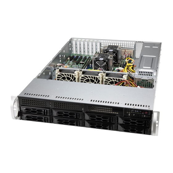
Chapter 1 Introduction 1.1 Overview The Supermicro SCLA25, is an all-purpose chassis. It will serve well in data centers, government labs, or business enterprises, for cloud and virtualization, simulation, automation, hosting and storage. In addition to the motherboard and chassis, several included parts are listed below. -
Page 8: Chassis Features
Supermicro SCLA25 Chassis User's Manual 1.3 Chassis Features Control Panel The chassis front features a control panel to monitor node function and control power. Figure 1-1. Control Panel Control Panel Features Item Features Description The main power switch applies or removes primary power from the power supply Power button to the server but maintains standby power. -
Page 9: Front Features
Chapter 1: Introduction Front Features The front of the chassis includes eight hot-swap drive bays and the chassis control panel. Figure 1-2. Chassis Front View Front Chassis Features Item Feature Description Control Panel Described in previous section Drives Eight 3.5" hot-swap storage drive bays I/O panel (optional) Two USB ports and one COM port DVD drive bay (optional DVD drive) Bay for an optional slim DVD drive... -
Page 10: Chapter 2 Rack Installation
Supermicro SCLA25 Chassis User's Manual Chapter 2 Rack Installation This chapter provides advice and instructions for optionally mounting your system in a rack. Please contact your sales representative to order optional mounting rails for your chassis. 2.1 Preparing for Setup The box in which the system was shipped should include the hardware needed to install it into the rack. -
Page 11: Server Precautions
Chapter 2 Rack Installation Server Precautions • Review the electrical and general safety precautions in the appendix, "Standardized Safety Warnings" in this manual. • Determine the placement of each component in the rack before you install the rails. • Install the heaviest server components at the bottom of the rack first and then work your way up. -
Page 12: Reliable Ground
Supermicro SCLA25 Chassis User's Manual Reliable Ground A reliable ground must be maintained at all times. To ensure this, the rack itself should be grounded. Particular attention should be given to power supply connections other than the direct connections to the branch circuit (i.e. the use of power strips, etc.). -
Page 13: Installing The Rails
Chapter 2 Rack Installation 2.2 Installing the Rails This section provides information on installing the chassis into a rack unit with the rails provided. There are a variety of rack units on the market, which may mean that the assembly procedure will differ slightly from the instructions provided. -
Page 14: Releasing The Inner Rail
Supermicro SCLA25 Chassis User's Manual Releasing the Inner Rail Each inner rail has a locking latch. This latch prevents the server from coming completely out of the rack when when the chassis is pulled out for servicing. To mount the rail onto the chassis, first release the inner rail from the outer rails. -
Page 15: Installing The Inner Rails
Chapter 2 Rack Installation Installing the Inner Rails Begin the rack mounting procedure by installing the inner rails to the chassis. 1. Identify the left and right inner rails. They are labeled. 2. Place the inner rail firmly against the side of the chassis, aligning the hooks on the side of the chassis with the holes in the inner rail. -
Page 16: Installing The Outer Rails Onto The Rack
Supermicro SCLA25 Chassis User's Manual Installing the Outer Rails onto the Rack 1. Press upward on the locking tab at the rear end of the middle rail. 2. Push the middle rail back into the outer rail. 3. Hang the hooks on the front of the outer rail onto the square holes on the front of the rack. -
Page 17: Installing The Chassis Into A Rack
Chapter 2 Rack Installation 2.3 Installing the Chassis into a Rack Once rails are attached to the chassis and the rack, you can install the server. 1. Pull the middle rail out of the front of the outer rail and make sure that the ball bearing shuttle is locked at the front of the middle rail. -
Page 18: Removing The Chassis From The Rack
Supermicro SCLA25 Chassis User's Manual Removing the Chassis from the Rack Caution! It is dangerous for a single person to off-load the heavy chassis from the rack without assistance. Be sure to have sufficient assistance supporting the chassis when removing it from the rack. -
Page 19: Chapter 3 Maintenance And Component Installation
Chapter 3: Maintenance and Component Installation Chapter 3 Maintenance and Component Installation This chapter provides instructions on installing and replacing main system components. To prevent compatibility issues, only use components that match the specifications and/or part numbers given. Installation or replacement of most components require that power first be removed from the system. -
Page 20: Accessing The System
Supermicro SCLA25 Chassis User's Manual 3.2 Accessing the System A portion of the chassis top is removable to allow access to components. Removing the Top Cover 1. Remove the screw on each side of the chassis. 2. Depress the release buttons and slide the cover back and off. -
Page 21: Chassis Components
Chapter 3: Maintenance and Component Installation 3.3 Chassis Components Storage Drives The SCLA25 chassis supports eight hot-swap 3.5" and two rear 2.5" SATA3 storage drives (HDDs or SSDs) in drive carriers to simplify their removal from the chassis. These carriers also help promote proper airflow. -
Page 22: Installing Drives
Supermicro SCLA25 Chassis User's Manual Installing Drives Removing Drive Carriers from the Chassis 1. Press the release button on the drive carrier. This extends the drive carrier handle. 2. Use the handle to pull the carrier out of the chassis. -
Page 23: Drive
Chapter 3: Maintenance and Component Installation Installing a 3.5" or 2.5" Hard Drive 1. Place the hard drive carrier on a flat surface. 2. Insert a 3.5" hard drive in an angle into the carrier, so that the mounting holes on the right side of the drive align with the two stubs in the drive carrier. -
Page 24: Dvd Drive Installation (Optional)
Supermicro SCLA25 Chassis User's Manual DVD Drive Installation (Optional) The system accommodates an optional slim DVD drive. Side mounting brackets are typically required. Installing a DVD Drive 1. Power down the system as described in Section 3.1 and remove the chassis cover. -
Page 25: Installing Expansion Cards
Chapter 3: Maintenance and Component Installation Installing Expansion Cards The system can accommodate six low-profile PCI-E cards. The chassis has seven: the slot nearest the chassis center is not supported by this motherboard. Installing an Expansion Card 1. Power down the system and remove the cover. 2. -
Page 26: System Fans
Supermicro SCLA25 Chassis User's Manual System Fans Three hot-swap fans provide cooling. They can be replaced without powering down the system. Fan speed is controlled by a system temperature setting in IPMI. If a fan fails, the remaining fans will ramp up to full speed. The system can continue to run with a failed fan. Replace any failed fan at your earliest convenience with the same type and model. -
Page 27: Power Supply
Power Supply The chassis features redundant power supplies. The power modules can be changed without powering down the system. New units can be ordered directly from Supermicro or authorized distributors. These power supplies are auto-switching capable. This feature enables them to automatically sense the input voltage and operate at a 100-120v or 180-240v. -
Page 28: Appendix A Bpn-Sas3-825Tq Backplane
Supermicro SCLA25 Chassis User's Manual Appendix A BPN-SAS3-825TQ Backplane To avoid personal injury and property damage, carefully follow all the safety steps listed below when accessing your system or handling the components. A.1 ESD Safety Guidelines Electrostatic Discharge (ESD) can damage electronic com ponents. To prevent damage to your system, it is important to handle it very carefully. -
Page 29: Introduction To The Bpn-Sas3-825Tq Backplane
This manual reflects BPN-SAS3-825TQ Revision 1.0, the most current release available at the time of publication. Always refer to the Supermicro Web site at www.supermicro.com for the latest updates, compatible parts and supported configurations. -
Page 30: Front Connectors And Sas Ports
Supermicro SCLA25 Chassis User's Manual A.5 Front Connectors and SAS Ports ACT_IN SIDEBAND #2 +12V +12V BPN-SAS3-825TQ REV 1.0 BAR CODE JP29: 9072 RESET SIDEBAND #1 Figure A-1. Front Connectors Front Connectors SAS Ports 4-pin power connector: JP13 SAS Port #0... -
Page 31: Front Connector And Pin Definitions
Appendix A: BPN-SAS3-825TQ Backplane A.6 Front Connector and Pin Definitions #1 and #2 Backplane Main Power Connectors Backplane Main Power 4-Pin Connector Pin# Definition The 4-pin connectors, designated JP10, and JP13 provide +12V power to the backplane. See the table on the right for pin 2 and 3 Ground definitions. - Page 32 Supermicro SCLA25 Chassis User's Manual #8 and #9 Sideband Headers Sideband Headers Pin # Definition Pin # Definition The sideband headers are designated JP51 and JP52. For SGPIO: SDIN; Controller ID SES-2 to work properly, you must connect an 8-pin side-...
-
Page 33: Front Jumper Locations And Pin Definitions
Appendix A: BPN-SAS3-825TQ Backplane A.7 Front Jumper Locations and Pin Definitions JP43 ACT_IN SIDEBAND #2 +12V +12V JP36 JP29 BPN-SAS3-825TQ JP18 REV 1.0 BAR CODE JP50 JP37 JP38 JP33 JP34 JP29: 9072 RESET SIDEBAND #1 JP42 JP41 JP40 Figure A-3. Front Jumpers Explanation of Jumpers Connector To modify the operation of the backplane, jumpers can be... -
Page 34: Sgpio And I C Modes And Jumper Settings
Supermicro SCLA25 Chassis User's Manual SGPIO and I C Modes and Jumper Settings This backplane can utilize SGPIO or I C, which is the default mode and can be used without making changes to your jumpers. The following information describes which jumper must be configured to use SGPIO mode. -
Page 35: Sas Port Connections In I
Appendix A: BPN-SAS3-825TQ Backplane SAS Port Connections in I C and SGPIO Settings Use the following chart when connecting this backplane. If the SAS ports are connected out of order, it will not be easy to identify drives using the LED function. SAS Port Connections in I C and SGPIO Settings Port #... -
Page 36: Rear Connectors And Led Indicators
Supermicro SCLA25 Chassis User's Manual A.8 Rear Connectors and LED Indicators SAS #5 SAS #4 SAS #6 SAS #7 SAS #3 SAS #1 SAS #2 SAS #0 Figure A-4. Rear Connectors and LEDs Rear SAS/SATA Connectors Rear SAS Drive Rear... -
Page 37: Appendix B Standardized Warning Statements For Ac Systems
Supermicro's Technical Support department for assistance. Only certified technicians should attempt to install or configure components. Read this appendix in its entirety before installing or configuring components in the Supermicro chassis. These warnings may also be found on our website at http://www.supermicro.com/about/... - Page 38 Appendix B: Standardized Warning Statements Warnung WICHTIGE SICHERHEITSHINWEISE Dieses Warnsymbol bedeutet Gefahr. Sie befinden sich in einer Situation, die zu Verletzungen führen kann. Machen Sie sich vor der Arbeit mit Geräten mit den Gefahren elektrischer Schaltungen und den üblichen Verfahren zur Vorbeugung vor Unfällen vertraut. Suchen Sie mit der am Ende jeder Warnung angegebenen Anweisungsnummer nach der jeweiligen Übersetzung in den übersetzten Sicherheitshinweisen, die zusammen mit diesem Gerät ausgeliefert wurden.
- Page 39 Supermicro SCLA25 Chassis User's Manual . ٌ ا ك ً ف حالة و ٌ يك أى تتسبب ف اصابة جسذ ة ٌ هذا الزهز ع ٌ خطز !تحذ ز قبل أى تعول عىل أي هعذات،يك عىل علن بالوخاطز ال ا ٌجوة عي الذوائز...
- Page 40 Appendix B: Standardized Warning Statements Warnung Vor dem Anschließen des Systems an die Stromquelle die Installationsanweisungen lesen. ¡Advertencia! Lea las instrucciones de instalación antes de conectar el sistema a la red de alimentación. Attention Avant de brancher le système sur la source d'alimentation, consulter les directives d'installation. .יש...
- Page 41 Supermicro SCLA25 Chassis User's Manual Warnung Dieses Produkt ist darauf angewiesen, dass im Gebäude ein Kurzschluss- bzw. Überstromschutz installiert ist. Stellen Sie sicher, dass der Nennwert der Schutzvorrichtung nicht mehr als: 250 V, 20 A beträgt. ¡Advertencia! Este equipo utiliza el sistema de protección contra cortocircuitos (o sobrecorrientes) del edificio.
- Page 42 Appendix B: Standardized Warning Statements Power Disconnection Warning Warning! The system must be disconnected from all sources of power and the power cord removed from the power supply module(s) before accessing the chassis interior to install or remove system components. 電源切断の警告...
- Page 43 Supermicro SCLA25 Chassis User's Manual يجب فصم اننظاو من جميع مصادر انطاقت وإ ز انت سهك انكهرباء من وحدة امداد انطاقت قبم انىصىل إىن امنناطق انداخهيت نههيكم نتثبيج أو إ ز انت مكىناث الجهاز 경고! 시스템에 부품들을 장착하거나 제거하기 위해서는 섀시 내부에 접근하기 전에 반드시 전원...
- Page 44 Appendix B: Standardized Warning Statements Attention Il est vivement recommandé de confier l'installation, le remplacement et la maintenance de ces équipements à des personnels qualifiés et expérimentés. !אזהרה .צוות מוסמך בלבד רשאי להתקין, להחליף את הציוד או לתת שירות עבור הציוד واملدربيه...
- Page 45 Supermicro SCLA25 Chassis User's Manual Warnung Diese Einheit ist zur Installation in Bereichen mit beschränktem Zutritt vorgesehen. Der Zutritt zu derartigen Bereichen ist nur mit einem Spezialwerkzeug, Schloss und Schlüssel oder einer sonstigen Sicherheitsvorkehrung möglich. ¡Advertencia! Esta unidad ha sido diseñada para instalación en áreas de acceso restringido. Sólo puede obtenerse acceso a una de estas áreas mediante la utilización de una herramienta especial,...
- Page 46 Appendix B: Standardized Warning Statements Battery Handling Warning! There is the danger of explosion if the battery is replaced incorrectly. Replace the battery only with the same or equivalent type recommended by the manufacturer. Dispose of used batteries according to the manufacturer's instructions 電池の取り扱い...
- Page 47 Supermicro SCLA25 Chassis User's Manual هناك خطر من انفجار يف حالة اسحبذال البطارية بطريقة غري صحيحة فعليل اسحبذال البطارية فقط بنفس النىع أو ما يعادلها مام أوصث به الرشمة املصنعة جخلص من البطاريات املسحعملة وفقا لحعليامت الرشمة الصانعة 경고! 배터리가 올바르게 교체되지 않으면 폭발의 위험이 있습니다. 기존 배터리와 동일하거나 제...
- Page 48 Appendix B: Standardized Warning Statements ¡Advertencia! Puede que esta unidad tenga más de una conexión para fuentes de alimentación. Para cortar por completo el suministro de energía, deben desconectarse todas las conexiones. Attention Cette unité peut avoir plus d'une connexion d'alimentation. Pour supprimer toute tension et tout courant électrique de l'unité, toutes les connexions d'alimentation doivent être débranchées.
- Page 49 Supermicro SCLA25 Chassis User's Manual Backplane Voltage Warning! Hazardous voltage or energy is present on the backplane when the system is operating. Use caution when servicing. バックプレーンの電圧 システムの稼働中は危険な電圧または電力が、 バックプレーン上にかかっています。 修理する際には注意く ださい。 警告 当系统正在进行时,背板上有很危险的电压或能量,进行维修时务必小心。 警告 當系統正在進行時,背板上有危險的電壓或能量,進行維修時務必小心。 Warnung Wenn das System in Betrieb ist, treten auf der Rückwandplatine gefährliche Spannungen oder Energien auf.
- Page 50 Appendix B: Standardized Warning Statements هناك خطز مه التيار الكهزبايئ أوالطاقة املىجىدة عىل اللىحة عندما يكىن النظام يعمل كه حذ ر ا عند خدمة هذا الجهاس 경고! 시스템이 동작 중일 때 후면판 (Backplane)에는 위험한 전압이나 에너지가 발생 합니다. 서비스 작업 시 주의하십시오. Waarschuwing Een gevaarlijke spanning of energie is aanwezig op de backplane wanneer het systeem in gebruik is.
- Page 51 Supermicro SCLA25 Chassis User's Manual תיאום חוקי החשמל הארצי !אזהרה .התקנת הציוד חייבת להיות תואמת לחוקי החשמל המקומיים והארציים تركيب املعدات الكهربائية يجب أن ميتثل للقىاويه املحلية والىطىية املتعلقة بالكهرباء 경고! 현 지역 및 국가의 전기 규정에 따라 장비를 설치해야 합니다.
- Page 52 Appendix B: Standardized Warning Statements Attention La mise au rebut ou le recyclage de ce produit sont généralement soumis à des lois et/ou directives de respect de l'environnement. Renseignez-vous auprès de l'organisme compétent. סילוק המוצר !אזהרה .סילוק סופי של מוצר זה חייב להיות בהתאם להנחיות וחוקי המדינה التخلص...
- Page 53 Supermicro SCLA25 Chassis User's Manual Warnung Gefährlich Bewegende Teile. Von den bewegenden Lüfterblätter fern halten. Die Lüfter drehen sich u. U. noch, wenn die Lüfterbaugruppe aus dem Chassis genommen wird. Halten Sie Finger, Schraubendreher und andere Gegenstände von den Öffnungen des Lüftergehäuses entfernt.
- Page 54 Verbindungskabeln, Stromkabeln und/oder Adapater, die Ihre örtlichen Sicherheitsstandards einhalten. Der Gebrauch von anderen Kabeln und Adapter können Fehlfunktionen oder Feuer verursachen. Die Richtlinien untersagen das Nutzen von UL oder CAS zertifizierten Kabeln (mit UL/CSA gekennzeichnet), an Geräten oder Produkten die nicht mit Supermicro gekennzeichnet sind.
- Page 55 .قيرح وأ لطع يف ببستي دق ىرخأ تالوحمو تالباك يأ مادختسا .ميلسلا سباقلاو لصوملا مجح لبق نم ةدمتعملا تالباكلا مادختسا تادعملاو ةيئابرهكلا ةزهجألل ةمالسلا نوناق رظحيUL وأCSA ( ةمالع لمحت يتلاوUL/CSA) لبق نم ةددحملاو ةينعملا تاجتنملا ريغ ىرخأ تادعم يأ عمSupermicro.
- Page 56 Disclaimer (cont.) The products sold by Supermicro are not intended for and will not be used in life support systems, medical equipment, nuclear facilities or systems, aircraft, aircraft devices, aircraft/emergency communication devices or other critical systems whose failure to perform be reasonably expected to result in significant injury or loss of life or catastrophic property damage.
- Page 57 Disclaimer (cont.) The products sold by Supermicro are not intended for and will not be used in life support systems, medical equipment, nuclear facilities or systems, aircraft, aircraft devices, aircraft/emergency communication devices or other critical systems whose failure to perform be reasonably expected to result in significant injury or loss of life or catastrophic property damage.
Need help?
Do you have a question about the SCLA25 and is the answer not in the manual?
Questions and answers