Vallox 096 MV Manual
Hide thumbs
Also See for 096 MV:
- User manual (66 pages) ,
- Instructions for use, maintenance and installation manual (64 pages) ,
- Manual (109 pages)

Related Manuals for Vallox 096 MV


Summary of Contents for Vallox 096 MV
- Page 1 Model Document Vallox 096 MV D5326 Vallox 110 MV Vallox 145 MV Valid from 17.03.2020 Type A3722 Updated A3702 05.02.2020 A3712 Manual Ventilation units...
-
Page 2: Table Of Contents
Vallox Silent Klick siphon ........ -
Page 3: Safety
INTENDED USE All Vallox ventilation units have been designed to provide appropriate and continuous ventilation so as to present no threat to health and to maintain structures in good condition. IMPORTANT In order to ensure that the indoor air presents no harm to health and remains optimal also for the structures of the building, ventilation must be kept on without disruptions. -
Page 4: Safety Signs Used In The Instructions
Vallox 145 MV have an additional heater. vary from country to • In Vallox 096 MV, there is a sealing tape at the bottom of the heat country. recovery cell. In other models, there is a separate sealing bar under the heat recovery cell. -
Page 5: Ventilation Unit Control
For the MyVallox Cloud/ Home instructions, Ventilation unit control options. please go to www. techmanuals.info/ ValloxMV/ENG/ Operation of the Vallox ventilation unit can be controlled by the onlinehelp/webhelp following means: • Through the My Vallox Control panel installed in the building. •... -
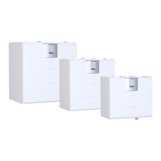
Page 6: Main Parts
MAIN PARTS Vallox 096 MV, Vallox 110 MV, and Vallox 145 MV R model in the figure Extract air fan Safety switch (behind the protective cover) Supply air fan Internal humidity sensor (behind the protective cover) Fine filter for supply air... -
Page 7: Installation
30 mm. Note that during mounting the unit rises 10 mm higher than the final height. Mount Vallox 096 MV, 110 MV, and Vallox 145 MV on the wall with a mounting plate, as shown in the adjacent figure. Make sure that the unit is horizontally level after mounting. -
Page 8: Installing The Ventilation Unit To The Ceiling Mounting Plate
Installing the ventilation unit to the ceiling mounting plate Install the ceiling mounting plate with M8 thread bars so that it is horizontally level. NOTE The end of the thread bars must be 5 mm or less below the fastening nut. Do not fasten the ceiling mounting plate too tight to the ceiling. -
Page 9: Vallox 145 Mv
MOUNTING ON A BASE NOTE Vallox 145 MV must always be installed on a base on the floor, or on the wall using a mounting plate. The base is optional. Adjust the base with adjusting legs to level it. Remove the (4 pcs) rubber plugs at the bottom of the unit. -
Page 10: Removal Of Condensing Water
REMOVAL OF CONDENSING WATER NOTE The Vallox Silent Klick siphon package is delivered with the unit. Installation instructions for the siphon are enclosed with the packaging, and can also be found online at www.vallox. com. When the alternative siphon installation method is used, the ring seal and the locking part must be moved to the pipe connection part that is mounted on the wall. -
Page 11: Dimensions And Duct Outlets
3. Supply air from the unit to the apartment Measurement points after the outlet collar. The fan curves indicate the total pressure accounted for by duct losses. 4. Extract air from the apartment to the unit © Vallox Oy - All rights reserved... -
Page 12: Vallox 110 Mv
Vallox 110 MV Main parts Dimensions and duct outlets Dimensions R model in the figure. In the L model, the parts are mirrored 1. Extract air fan 6. Coarse filter for supply air (behind the protective cover) 7. Coarse filter for extract air 2. -
Page 13: Vallox 145 Mv
3. Supply air from the unit to the Extract air apartment Measurement points after the outlet collar. The fan curves indicate 4. Extract air from the apartment to the unit the total pressure accounted for by duct losses. © Vallox Oy - All rights reserved... -
Page 14: Maintenance
To replace the filters: Disconnect the ventilation unit from the mains electricity supply. 2. Lift the latch to open the door of the Vallox ventilation NOTE unit. 3. Lift the door off. Vallox 096 MV: The... -
Page 15: Cleaning The Heat Recovery Cell
To check and clean the heat recovery cell: Disconnect the ventilation unit from the mains electricity supply. 2. Open the Vallox ventilation unit door by first lifting the latch fully up and then lowering it back a little way. 3. Lift the door off. -
Page 16: Cleaning The Fans
Disconnect the ventilation unit from the mains electricity supply. 2. Lift the latch to open the door of the Vallox ventilation unit. 3. Lift the door off. CAUTION The door is heavy. 4. Remove the extract air filter (C), the cell top bracket (E) and the heat recovery cell (D). - Page 17 12. Close the door. Ensure that the safety switch catch of the door is touching the safety switch. 13. Plug the ventilation unit back into the mains. The fan has now been checked and cleaned. © Vallox Oy - All rights reserved...
-
Page 18: Cleaning The Extract Air Fan
Cleaning the extract air fan To clean the extract air fan, proceed as follows: Disconnect the ventilation unit from the mains electricity supply. 2. Lift the latch to open the door of the Vallox ventilation unit. 3. Lift the door off. CAUTION The door is heavy. -
Page 19: Technical Specifications
4000 8000 , dB(A) Sound pressure level coming through the envelope of the unit in the room in which it is installed (10m² sound absorption) Adjustment position Adjustment position (%) , dB (A) © Vallox Oy - All rights reserved... - Page 20 TECHNICAL SPECIFICATIONS Product title Product number Vallox 110 MV R 3446650 Vallox 110 MV L 3446750 Air volumes Fans Supply air 107 dm /s, 100 Pa Supply air 0,119 kW 0,9 A EC Extract air 113 dm /s, 100 Pa...
- Page 21 4000 8000 , dB(A) Sound pressure level coming through the envelope of the unit in the room in which it is installed (10m² sound absorption) Adjustment position Adjustment position (%) , dB (A) © Vallox Oy - All rights reserved...
-
Page 22: Internal Electrical Connection
INTERNAL ELECTRICAL CONNECTION Vallox 096 MV 230V 50Hz MB_A MB_A MB_B MB_B +24V +24V RS_A RS_A RS_B RS_B TESTER +24V +24V RS_A RS_A RS_B RS_B +11V1 +24V AN/I D/I1 RM/I +24V RH% CO2 D/I2 RM/O 1 2 3 4 5 6 130°C... -
Page 23: Vallox 110 Mv, And Vallox 145 Mv
Vallox 110 MV, and Vallox 145 MV 230V 50Hz MB_A MB_A MB_B MB_B +24V +24V RS_A RS_A RS_B RS_B TESTER +24V +24V RS_A RS_A RS_B RS_B +11V1 +24V AN/I D/I1 +24V RM/I RH% CO2 RM/O D/I2 1 2 3 4 5 6 90°C... -
Page 24: External Electrical Connection
EXTERNAL ELECTRICAL CONNECTION 7028350 2014-08-29 JS MyVallox MyVallox REMOTE Control MONITORING 0.3W sensor Modbus RTU 2x2x0,5+0,5 2x2x0,5+0,5 MyVallox CO 2 MyVallox 2x2x0,5+0,5 sensor Control 1.2W 2x2x0,5+0,5 2x2x0,5+0,5 External temperature Analog input sensor two different 2x0,5 2x0,5 NTC 4K7 functions 2x0,5 2x0,5 2x0,5 Potential-free contact... -
Page 25: External Electrical Connection For Controlling The Mlv Duct Radiator
Digital and analog ground potential RM/I 24V relay input RS_A Local hardware Modbus A signal RM/O 24V relay output RS_B Local hardware Modbus B signal Circulation pump External temperature sensor connector Solenoid valve D/I1 Digital input 1 © Vallox Oy - All rights reserved... -
Page 26: Duct Radiator Operation
DUCT RADIATOR OPERATION Always follow first and foremost the connection diagram provided by the HVAC designer or heat pump If the duct NOTE: manufacturer. Also read the duct radiator manual. radiator is used in the supply air duct, it The accompanying figure shows an example of the can only be used for arrangement for connecting the heating/cooling radiator cooling. -
Page 27: Duct Radiator Operation Chart
De-aerator. Not included in the delivery. External electrical junction box for the MV Feed from the distribution board External NTC sensor for Vallox MV ventilation units Air extraction 24 VDC relay/contactor for controlling the pump and the solenoid valve. Not included in Duct radiator (reverse connection) the delivery. -
Page 28: Exploded View And Parts List
EXPLODED VIEW AND PARTS LIST Vallox 096 MV PART CODE PART CODE PART CODE Supply / extract air fan HR cell bypass Post-heating resistor 1108800 942210 (with a hood) damper assembly 900W (R and L models) 935365 R model 3491200... -
Page 29: Vallox 110 Mv
949111 sensor (optional) Coarse filter for Post-heating resistor MyVallox VOC sensor 978043 949112 extract air 900W (optional) Ceiling bushing for electric 950445 R model 942211 wires Ceiling feed-through seal 950446 L model 942210 © Vallox Oy - All rights reserved... -
Page 30: Vallox 145 Mv
Vallox 145 MV NO. PART CODE NO. PART CODE NO. PART CODE Supply / extract air HR cell bypass damper 1109200 Post-heating resistor 900W fan (with a hood) assembly 935285 R model 3475900 R model 942211 Wall mounting 3482100 L model... -
Page 31: Conformity Certificates
CONFORMITY CERTIFICATES... - Page 32 Vallox Oy | Myllykyläntie 9-11 | 32200 LOIMAA | FINLAND Customer service +358 10 7732 200 | Aftersales +358 10 7732 270...
Need help?
Do you have a question about the 096 MV and is the answer not in the manual?
Questions and answers