Table of Contents
Advertisement
Manual
Ventilation units
Model
Vallox TSK Multi 50 MV
Vallox TSK Multi 50 MV EH
Vallox TSK Multi 80 MV
Vallox TSK Multi 80 MV EH
Vallox TSK Multi 80 MV EHX
Vallox 90 MV
Vallox 90K MV
Vallox 096 MV
Vallox 101 MV
Vallox 110 MV
Vallox 145 MV
Vallox 245 MV
Vallox 245 MV VKL
Document
D3768
Valid from
3.2.2015
Updated
9.1.2018
Advertisement
Table of Contents

Related Manuals for Vallox Vallox TSK Multi 80 MV


Summary of Contents for Vallox Vallox TSK Multi 80 MV
- Page 1 Document Vallox TSK Multi 50 MV D3768 Vallox TSK Multi 50 MV EH Vallox TSK Multi 80 MV Valid from Vallox TSK Multi 80 MV EH 3.2.2015 Vallox TSK Multi 80 MV EHX Vallox 90 MV Updated Vallox 90K MV 9.1.2018...
- Page 2 CONTENTS NOTE You can register your Vallox MV ventilation unit with the MyVallox Cloud cloud service and sign in into your MyVallox Cloud account at www.myvallox.com. INTRODUCTION Away Boost Safety Fireplace profile Installation Symbols for ventilation profiles Guarantee Changing the profile...
- Page 3 Cleaning the supply air fan TECHNICAL DATA Cleaning the extract air fan Vallox 245 MV Vallox TSK Multi 50 MV ja Vallox TSK Multi 80 MV Before beginning maintenance work Vallox 90 MV ja Vallox 90K MV Replacing the filters (User)
-
Page 4: Safety
Structural or electronic modifications or changes made to the software INTENDED USE All Vallox ventilation units have been designed to provide appropriate and continuous ventilation so as to present no threat to health and to maintain structures in good condition. -
Page 5: Safety Signs Used In The Instructions
Vallox 245 MV VKL has a water circulation post-heating radiator and two electric 1500W additional heating radiators. • In Vallox 096 MV, there is a sealing tape at the bottom of the heat recovery cell. In other models, there is a separate sealing bar under the heat recovery cell. •... -
Page 6: Main Parts
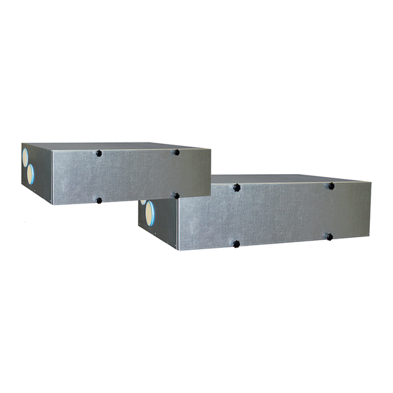
MAIN PARTS VALLOX TSK MULTI 50 MV AND VALLOX TSK MULTI 80 MV R model in the figure Supply air fan Bypass flap Extract air fan Safety switch Post-heating radiator Control panel Heat recovery cell Carbon dioxide sensor Supply air filter F7... -
Page 7: Vallox 90 Mv
Extract air fan Post-heating radiator Supply air fan Safety switch Supply air filter F7 Control panel Heat recovery cell Carbon dioxide sensor Automatic summer/winter damper Humidity sensor Supply air filter G4 Extract air filter G4 © Vallox Oy - All rights reserved... -
Page 8: Vallox 90K Mv
MAIN PARTS VALLOX 90K MV R model in the figure Extract air fan Post-heating radiator Supply air fan Safety switch Supply air filter F7 Control panel Heat recovery cell Carbon dioxide sensor Automatic summer/winter damper Humidity sensor Supply air filter G4... -
Page 9: Vallox 096 Mv, Vallox 110 Mv, And Vallox 145 Mv
MAIN PARTS VALLOX 096 MV, VALLOX 110 MV, AND VALLOX 145 R model in the figure Extract air fan (behind the protective cover) Post-heating radiator (behind the extract air duct) Supply air fan (behind the extract air duct) Safety switch... -
Page 10: Vallox 101 Mv
MAIN PARTS VALLOX 101 MV R model in the figure Extract air fan Post-heating radiator (in the supply air duct) Supply air fan Safety switch Supply air filter F7 Control panel Heat recovery cell Carbon dioxide sensor Bypass flap Humidity sensor... -
Page 11: Vallox 245 Mv
Supply air filter F7 Carbon dioxide sensor Heat recovery cell, 2 pcs Humidity sensor Bypass flap Internal humidity sensor (behind the electric box) Supply air filter G4 Post-heating liquid radiator Extract air filter G4 Post-heating radiator © Vallox Oy - All rights reserved... -
Page 12: Ventilation Unit Control
At the same time you create a MyVallox Cloud account for yourself. Read more about the service at www.myvallox.com. Ventilation unit control options Operation of the Vallox ventilation unit can be controlled by The MyVallox Control control the following means: panel automatically switches to •... - Page 13 VENTILATION UNIT CONTROL SYSTEM DESCRIPTION MyVallox Cloud Vallox MV Modbus MyVallox Control Internet 2. WLAN 3. Router 4. WLAN/LAN 5. Additional switch 6. Sensors © Vallox Oy - All rights reserved...
- Page 14 VENTILATION UNIT CONTROL CONTROL PANEL BUTTONS BUTTON DESCRIPTION The Change profile button changes the ventilation profile or the operating status used. The Profile information button allows you to view the currently active profile information. The Temperature button displays temperature and sensor information.
-
Page 15: Unit Software
Unit software We recommend that the latest software version be always used. Check and download the latest version at http://www.vallox.com or at cloud.vallox.com either before or immediately after startup. The current software version of the ventilation unit is shown on the control panel display when the unit is connected to the mains or factory settings are restored. -
Page 16: Setup Wizard
The qualified ventilation installer must complete the fan settings in accordance with the ventilation plan. Do not change these settings. Start the Vallox ventilation unit. 2. When the unit is started for the first time, the language menu opens on the control panel display. Select OK. -
Page 17: Set The Date
OK to proceed to the expert settings of the ventilation unit. Select Back to use the ventilation unit on factory settings and complete the configuration of the expert settings later. NOTE Expert settings are settings that use e.g. airflow measurement equipment. © Vallox Oy - All rights reserved... -
Page 18: Expert Settings
EXPERT SETTINGS Lock code and access rights NOTE The default lock code is 0000, i.e. the lock code inquiry is turned off. Enter the first digit of the lock code using the Up arrow and Down arrow buttons. Proceed to the next digit by selecting Right arrow. -
Page 19: Basic Fan Settings
Any later changes will be saved as user settings. Both the setup and user settings can be restored later even if the settings had been modified later. © Vallox Oy - All rights reserved... -
Page 20: Expert Settings
EXPERT SETTINGS PROFILE SETTINGS NOTE By default, the At home profile uses the higher basic ventilation fan speed. We recommend that this basic ventilation setting be used with the At home profile. Once you have set the fan speed for the At home profile, the fan speed for the Away profile will by default be set to -30% of the At home profile fan speed. -
Page 21: Fireplace Profile
To change any of the set values, use the arrow buttons to return to the desired line and then press OK. 2. When you are satisfied with the settings, use the arrow buttons to select Start and then press OK. © Vallox Oy - All rights reserved... -
Page 22: Four Ventilation Unit Profiles
USING THE UNIT VENTILATION PROFILES FOUR VENTILATION UNIT PROFILES At home Use this ventilation profile when the dwelling or the premises Using the At home, Away, and are occupied. Boost profiles according to Away need helps to save energy. Use this ventilation profile when the dwelling or premises are unoccupied, e.g. -
Page 23: Changing The Profile
Carbon dioxide — Indicates the highest carbon dioxide level • measured by the sensors. Replace filters — Indicates the next recommended filter • replacement date. Time in operation — Indicates how long the device has been • running. © Vallox Oy - All rights reserved... -
Page 24: Viewing The Fireplace Profile Information
VENTILATION PROFILES Viewing the Fireplace profile information Open the main display of the Fireplace profile: 2. Select Profile information. 3. The information display shows the following information: • Duration — Indicates the duration of enhanced ventilation when the Fireplace profile is activated. The value is expressed in hours and minutes. -
Page 25: Viewing Temperature Data
8. To exit the menu, press the Back button. You can view the graph for a week or for a single day. © Vallox Oy - All rights reserved... -
Page 26: Relative Humidity Of Air And Carbon Dioxide Level Statistics
3. Use the Plus and Minus buttons to alternate between weekly and daily statistics. 4. To exit the menu, press the Back button. NOTE For more detailed instructions, go to www.vallox.com Relative humidity of air and carbon dioxide level statistics 1 day 1 day 1 week 1 week Relative humidity of air statistics for the past 24 hours. -
Page 27: Filter Settings
5. Use the Plus and Minus buttons to set the desired reminder interval in months in the Reminder interval field. The interval value can be between 1 and 12 months. The default setting is 4 months. 6. Select OK. © Vallox Oy - All rights reserved... -
Page 28: Filter Maintenance Reminder
SETTINGS Filter maintenance reminder The maintenance reminder reminds you of the filter replacement with a pop-up window. The message can be acknowledged by selecting OK. Press the clock button to postpone the reminder for one week. DISPLAY SETTINGS Setting the sleep time Select Settings >... -
Page 29: Time And Date
Select Settings > Time and date. 2. Select OK. 3. Select Right arrow until the 3/4 display opens. 4. Select Plus. The Dayl.saving time setting value is changed to Off. 5. Select OK. © Vallox Oy - All rights reserved... -
Page 30: Setting The Date
SETTINGS Setting the date Select Settings > Time and date. 2. Select OK. 3. Select Right arrow until the 4/4 display opens. 4. Use the Plus and Minus buttons to set the date. 5. Select Right arrow. 6. Use the Plus and Minus buttons to set the month. 7. -
Page 31: Setting And Editing The Weekly Program
Select Settings > Week clock on or Week clock off. 2. Select OK. 3. Select Settings. 4. Select Remove all settings. 5. Select OK to accept deletion of the weekly program. The weekly program has now been deleted. © Vallox Oy - All rights reserved... -
Page 32: Example Of Setting A Weekly Program
SETTINGS Example of setting a weekly program In this example, the following weekly program has been set: Mon-Fri 8-17, Away . • Mon-Fri 17-07, At home. • Sat 8-17, At home. • Sat 18-20, At home with a ventilation boost needed for •... -
Page 33: Troubleshooting
To check this, pour some water into the pool. Clean as WARNING required. Water must at all times be kept out of the electrical system. © Vallox Oy - All rights reserved... -
Page 34: Maintenance
• Class G4 coarse filter (C) filters the extract air and keeps the heat recovery cell clean. Using original Vallox filters ensures that the ventilation To replace the filters: unit remains in top condition, Disconnect the ventilation unit from the mains electricity giving the best results. -
Page 35: Cleaning The Heat Recovery Cell (User)
13. Plug the ventilation unit back into the mains. 14. The heat recovery cell has now been checked and cleaned. IMPORTANT If the unit has an enthalpy cell, it must not be washed. Only aluminium or plastic cells can be washed. © Vallox Oy - All rights reserved... -
Page 36: Cleaning The Fans (Installer)
CLEANING THE FANS (INSTALLER) Check the cleanliness of the fans when servicing the filters and the heat recovery cell. Clean the fans as required. You can clean the fan blades with compressed air (wear protective goggles) or by brushing them gently. Do not remove or move the fan blade balancing weights. -
Page 37: Cleaning The Extract Air Fan
13. Plug the ventilation unit back into the mains. The fan has now been checked and cleaned. NOTE Install the fan beds in a reverse order. © Vallox Oy - All rights reserved... -
Page 38: Before Beginning Maintenance Work
Using original Vallox filters ensures replace them if required. that the ventilation unit remains in top The Vallox ventilation unit has three air filters: condition, giving the best results. • Class G4 coarse filter filters insects, heavy pollen and other relatively large foreign objects out of the outdoor air. -
Page 39: Cleaning The Heat Recovery Cell (User)
9. Close the door and ensure that the safety switch catch of the door is engaged. 10. Plug the ventilation unit back into the mains. The heat recovery cell has now been checked and cleaned. © Vallox Oy - All rights reserved... -
Page 40: Cleaning The Fans (Installer)
Do not remove or move the fan Disconnect the ventilation unit from the mains electricity blade balancing weights. supply. 2. Lift the latch to open the door of the Vallox ventilation unit. 3. Lift the door off. CAUTION The door is heavy. -
Page 41: Before Beginning Maintenance Work
See section Vallox 90 MV, Replacing the filters. CLEANING THE HEAT RECOVERY CELL (USER) See section Vallox 90 MV, Cleaning the heat recovery cell. CLEANING THE FANS (INSTALLER) See section Vallox 90 MV, Cleaning the fans. CLEANING THE GREASE FILTER OF THE COOKER HOOD (USER) Clean the grease filter of the cooker hood 1-2 times a month. -
Page 42: Before Beginning Maintenance Work
The filter replacement interval depends on the ambient dust concentration. It is recommended that the filters be replaced every spring and autumn, or at the very least once a year. NOTE Using original Vallox filters ensures that the ventilation unit remains in top condition, giving the best results. -
Page 43: Cleaning The Heat Recovery Cell (User)
To replace the filters: IMPORTANT Disconnect the ventilation unit from the mains electricity supply. 2. Open door of the Vallox ventilation unit by undoing the finger screws. If the unit has an enthalpy cell, 3. Lift the door off. it must not be washed. Only... -
Page 44: Cleaning The Fans (Installer)
Handle the fan blades carefully. Disconnect the ventilation unit from the mains electricity supply. Do not remove or move the fan 2. Open door of the Vallox ventilation unit by undoing the finger screws. blade balancing weights. 3. Lift the door off. -
Page 45: Before Beginning Maintenance Work
It is recommended that the filters be replaced every spring and autumn, or at the very least once a year. NOTE Using original Vallox filters ensures that the ventilation unit remains in top condition, giving the best results. © Vallox Oy - All rights reserved... -
Page 46: Cleaning The Heat Recovery Cell (User)
To replace the filters: Disconnect the ventilation unit from the mains electricity supply. 2. Lift the latch to open the door of the Vallox ventilation unit. 3. Lift the door off. CAUTION The door is heavy. 4. Remove the old filters (A, B, C) and discard them. -
Page 47: Cleaning The Fans (Installer)
6. Remove the temperature sensor from the resistance support (figure 4). 7. Remove the additional and post-heating radiator support, which is attached by two wing nuts (Vallox 110 MV and Vallox 145 MV) or screws (Vallox 096 MV) from below (figure 5). - Page 48 8. Pull the radiator and the support out of the unit (figures 6 and 7) and remove the quick connector of the radiator wires. CAUTION Before removing the resistor from the unit, make sure it is not hot. 9. The fan can now be cleaned in place. It is recommended that the fan be cleaned in place, i.e.
-
Page 49: Cleaning The Extract Air Fan
Cleaning the extract air fan To clean the extract air fan, proceed as follows: Disconnect the ventilation unit from the mains electricity supply. 2. Lift the latch to open the door of the Vallox ventilation unit. 3. Lift the door off. CAUTION The door is heavy. -
Page 50: Before Beginning Maintenance Work
When the maintenance reminder becomes activated, check the cleanliness of the filters and replace them if required. The Vallox ventilation unit has three air filters: • Class G4 coarse filter filters insects, heavy pollen and other relatively large foreign objects out of the outdoor air. -
Page 51: Cleaning The Heat Recovery Cells (User)
The heat recovery cells have now been checked and Handle the cells carefully! For cleaned. example, do not lift the cells by the layers. The cell layers are very thin and easily damaged. © Vallox Oy - All rights reserved... -
Page 52: Cleaning The Fans (Installer)
CLEANING THE FANS (INSTALLER) Check the cleanliness of the fans when servicing the filters and the heat recovery cell. Clean the fans as required. You can clean the fan blades with compressed air (wear protective goggles) or by brushing them gently. NOTE Only the supply air fan is equipped with a sound-damping... -
Page 53: Removing The Resistor
WARNING Risk of fire! Connect the cables so that they do not touch the resistor. CAUTION Before removing the resistor from the unit, make sure it is not hot. © Vallox Oy - All rights reserved... -
Page 54: Installation
GENERAL INSTALLATION INSTRUCTIONS INSTALLATION SITE The Vallox ventilation unit must be installed in a location where the temperature remains above +10°C. When the unit is installed without a protective enclosure, the location must be chosen so that its noise does not cause any disturbance (e.g. storage premises, technical spaces, and false ceilings). -
Page 55: Installation Site
INSTALLATION SITE Vallox TSK Multi 50 MV and Vallox TSK Multi 80 MV must be mounted on the ceiling. Use the mounting hooks (4 pcs) delivered with the unit to mount the ventilation unit on the ceiling. Observe the weight of the unit (45 kg / 58.5 kg) when mounting. -
Page 56: Dimensions And Duct Outlets
DIMENSIONS AND DUCT OUTLETS UNIT DIMENSIONS Dimension Vallox TSK Vallox TSK Multi 50 MV Multi 80 MV 1026 100 (female) 125 (female) R model: L model: 1. Outdoor air to the unit 1. Extract air from the apartment to 2. Supply air from the unit to the... -
Page 57: Vallox 90 Mv
Make sure that the unit is horizontally level after mounting. MOUNTING ON THE CEILING Model Vallox 90 MV can be equipped with an optional ceiling mount plate. To attach the ceiling mounting plate: • To the ceiling with M8 thread bars so that they stand the weight of the unit. -
Page 58: Installing The Ventilation Unit To The Ceiling Mounting Plate
The accessories delivered with the unit include four airflow measuring tubes. These can be inserted in the ducts to allow for easier ventilation adjustment. DIMENSIONING OF AND SPACE REQUIRED FOR INSTALLATION OF THE VALLOX SILENT KLICK WATER SEAL... -
Page 59: Mounting On The Wall
WATER SEAL NOTE The Vallox Silent Klick water seal package is delivered with the unit. Installation instructions for the water seal are enclosed with the packaging, and can also be found online at www.vallox. com. When the alternative water seal installation method is used, the ring seal and the locking part must be moved to the pipe connection part that is mounted on the wall. -
Page 60: Mounting On The Wall
Make sure that the unit is horizontally level after mounting. MOUNTING ON THE CEILING Vallox 096 MV, Vallox 101 MV, and Vallox 110 MV can be equipped with an optional ceiling mount plate. To attach the ceiling mounting plate: •... -
Page 61: Installing The Ventilation Unit To The Ceiling Mounting Plate
(D) (4 pcs). 3. Install condensing water insulation (E) between the unit and the ceiling mounting plate. In the case of Vallox 110 MV install it on the outlet collars, and in the case 096 MV - 600mm of Vallox 096 MV install it directly on the 110 MV - 638mm ceiling installation plate. -
Page 62: Vallox 101 Mv
MOUNTING ON THE CEILING Vallox 101 MV can be equipped with an optional ceiling mount plate. To attach the ceiling mounting plate: • On rafter frames or other frame structure with M8 thread bars so that they withstand the weight of the unit. -
Page 63: Attic Floor Penetration Plate
Where required, the unit can be detached from the ceiling mounting plate. Lift the unit slightly upwards and pull simultaneously from both operating levers (C) of the ceiling mounting plate to detach the unit from the ceiling mounting plate. © Vallox Oy - All rights reserved... -
Page 64: Mounting On A Base (Vallox 145 Mv)
MOUNTING ON A BASE (VALLOX 145 NOTE Vallox 145 MV must always be installed on a base on the floor, or on the wall using a mounting plate. The base is optional. Adjust the base with adjusting legs to level it. -
Page 65: Water Seal
Vallox 096 MV Vallox 101 MV Vallox 110 MV Vallox 145 MV 147,5 147,5 Space required by the alternative Vallox Silent Klick water seal installation method (elbow) Vallox 096 MV Vallox 101 MV Vallox 110 MV Vallox 145 MV © Vallox Oy - All rights reserved... -
Page 66: Vallox 245 Mv
MOUNTING ON THE FLOOR Vallox 245 MV is always mounted on the floor. Adjust the adjusting legs so that the unit is level. MEASURING TUBES The accessories delivered with the unit include four airflow measuring tubes. These can be inserted in the ducts to allow for easier ventilation adjustment. - Page 67 18 % D View from above E Right side Volume flow rate AIR VOLUMES VALLOX TSK MULTI 50 MV, SUPPLY AIR (F7+G4), EXTRACT AIR (G4) Pressure loss in ducts. Total pressure (Pa) Volume flow rate (dm 100% extract air SFP: 2,0 / 0,56...
- Page 68 32.1 27.0 24.4 VALLOX TSK MULTI 80 MV Vallox TSK Multi 80 MV Product titles Vallox TSK Multi 80 MV EH Vallox TSK Multi 80 MV EHX Air volumes Extract air 0.071kW 0.5A 93 dm³/s 100 Pa Supply air 0.071kW 0,5A 76 dm³/s 100 Pa Electrical connection 230 V, 50 Hz, ~8.8 A...
- Page 69 28 % 18 % E Right side (l/s) Volume flow rate AIR VOLUMES VALLOX TSK MULTI 80 MV, SUPPLY AIR (F7+G4), EXTRACT AIR (G4) Pressure loss in ducts. Total pressure (Pa) Volume flow rate (dm 100% extract air SFP: 2,0 / 0,56...
- Page 70 TECHNICAL SPECIFICATIONS Product titles Product HVAC code Fans Supply air 0.119kW, 0.9A EC number Vallox 90 MV R 7912066 Extract air 0.119kW, 0.9A EC 3570600 Vallox 90 MV L 7912067 3570700 Air volumes Supply air 73 l/s, 100Pa Efficiencies Annual efficiency...
- Page 71 Air flow measurement points L model Measurement points after the outlet collar. The fan curves indicate the total pressure accounted for by duct losses. A Supply air B Extract air C Supply D Extract © Vallox Oy - All rights reserved...
-
Page 72: Vallox 096 Mv
TECHNICAL SPECIFICATIONS Product titles Product numbers HVAC code Additional heating – Vallox 096 MV R 3474450 7912030 radiator Vallox 096 MV L 3474550 7912031 Air volumes Supply air 92 l/s, 331m /h, 100Pa Fans Supply air 0.119kW, 0.9A EC Extract air... - Page 73 4. Extract air from the apartment to the unit A Supply air B Extract air Measurement points after the outlet collar. The fan curves indicate the total pressure accounted for by duct losses. © Vallox Oy - All rights reserved © Vallox Oy - All rights reserved...
-
Page 74: Vallox 101 Mv
TECHNICAL SPECIFICATIONS Product titles Product numbers HVAC code Additional heating – Vallox 101 MV R 4102189 7912119 radiator Vallox 101 MV L 4102197 7912120 Air volumes Supply air 90 l/s, 324 m3/h, 100 Pa Fans Supply air 0.115kW, 0.9A EC... - Page 75 3. Supply air from the unit to the apartment 4. Extract air from the apartment to the unit B Extract air Measurement points after the outlet collar. The fan curves indicate the total pressure accounted for by duct losses. © Vallox Oy - All rights reserved...
-
Page 76: Vallox 110 Mv
TECHNICAL SPECIFICATIONS Product titles Product numbers HVAC codes Additional heating Power, 900W Vallox 110 MV R 3446650 7912039 radiator Vallox 110 MV L 3446750 7912040 Air volumes Supply air 107 l/s, 386m /h, 100Pa Fans Supply air 0.119kW, 0.9A EC... - Page 77 4. Extract air from the apartment to the unit B Extract air Measurement points after the outlet collar. The fan curves indicate the total pressure accounted for by duct losses. © Vallox Oy - All rights reserved © Vallox Oy - All rights reserved...
-
Page 78: Vallox 145 Mv
TECHNICAL SPECIFICATIONS Product titles Product numbers HVAC codes Additional heating Power, 1500W Vallox 145 MV R 3475650 7912049 radiator Vallox 145 MV L 3475750 7912050 Air volumes Supply air 150 l/s, 540m /h, 100Pa Fans Supply air 0.175 kW, 1.25A... - Page 79 4. Extract air from the apartment to the unit A Supply air B Extract air Measurement points after the outlet collar. The fan curves indicate the total pressure accounted for by duct losses. © Vallox Oy - All rights reserved © Vallox Oy - All rights reserved...
-
Page 80: Vallox 245 Mv
TECHNICAL SPECIFICATIONS FAN INPUT POWER Product titles Product numbers HVAC code Vallox 245 MV R 3513100 7912051 Vallox 245 MV L 3513200 7912052 100% Air volumes 245dm3/s, 100Pa Supply air 267dm3/s, 100Pa Extract air 230V, 50Hz 14.5A (power plug) Electrical connection... - Page 81 7. Liquid radiator output (VKL model) A Supply air 8. Liquid radiator input (VKL model) B Extract air Measurement points after the connection outlet. The fan curves indicate the total pressure accounted for by duct losses. © Vallox Oy - All rights reserved...
-
Page 82: Vallox 245 Mv Vkl
FAN INPUT POWER TECHNICAL SPECIFICATIONS Product titles Product HVAC codes numbers Vallox 245 MV VKL R 7912059 3513150 Vallox 245 MV VKL L 7912060 3513250 100% Air volumes Supply air 219 dm3/s, 100 Pa Extract air 267 dm3/s, 100 Pa Electrical connection 230V, 50Hz 14.5A (power plug) - Page 83 Vallox 245 MV liquid radiator t =15 °C, t =40°C 3,00 8,00 0.100 0.100 0.050 0.050 7,00 2,50 6,00 0.020 2,00 0.020 5,00 4,00 1,50 3,00 1,00 2,00 0,50 1,00 0,00 0,00 20,0 40,0 60,0 10,0 20,0 30,0 © Vallox Oy - All rights reserved...
-
Page 84: Internal Electrical Connection
4. Exhaust air 130°C overheating protection 5. Supply air from the cell D/I2 Digital input 2 (Vallox TSK Multi 50 MV EH / Vallox TSK Multi 80 MV EH, EHX) 11V1 11.1 V operating voltage Additional heating radiator with 90°C and 130°C overheating protection... - Page 85 5. Supply air from the cell D/I2 Digital input 2 11V1 11.1 V operating voltage AN/I Analog input 0-10VDC RM/I 24V relay input CABLE COLOURS RM/O 24V relay output Blue Brown White Grey Yellow YEGN Yellow-green © Vallox Oy - All rights reserved...
- Page 86 5. Supply air from the cell D/I2 Digital input 2 130°C overheating protection 11V1 11.1 V operating voltage Hood connector AN/I Analog input 0-10VDC Vallox 90 K SC Hood RM/I 24V relay input RM/O 24V relay output CABLE COLOURS Black Blue Brown...
- Page 87 11.1 V operating voltage AN/I Analog input 0-10VDC RM/I 24V relay input CABLE COLOURS RM/O 24V relay output Black Blue Brown White Grey Yellow YEGN Yellow-green © Vallox Oy - All rights reserved © Vallox Oy - All rights reserved...
- Page 88 INTERNAL ELECTRICAL CONNECTION 230 V 50 Hz MB_A MB_A MB_B MB_B +24V +24V RS_A RS_A RS_B RS_B TESTER +24V +24V RS_A RS_A RS_B RS_B +11V1 +24V AN/I D/I1 RM/I +24V D/I2 RM/O 1 2 3 4 5 6 Motherboard MB_A External Modbus A signal Supply air fan MB_B...
- Page 89 11.1 V operating voltage Additional heating radiator with 90°C and 130°C overheating AN/I Analog input 0-10VDC protection CABLE COLOURS RM/I 24V relay input Black RM/O 24V relay output Blue Brown White Grey Yellow YEGN Yellow-green © Vallox Oy - All rights reserved...
-
Page 90: External Electrical Connection
EXTERNAL ELECTRICAL CONNECTION 7028350 MyVallox 2014-08-29 JS REMOTE MyVallox 0.3W MONITORING Control transmitter Modbus RTU 2x2x0,5+0,5 2x2x0,5+0,5 MyVallox transmitter 1.2W MyVallox 2x2x0,5+0,5 Control 2x2x0,5+0,5 2x2x0,5+0,5 External temperature Analog input sensor two different 2x0,5 2x0,5 NTC 4K7 functionalities 2x0,5 2x0,5 2x0,5 Potential-free contact data 24VDC can be programmed to display... -
Page 91: Duct Radiator Operation Chart
In this case, the pump and the solenoid valve limit value set at the factory (-5 °C). can be controlled using a Vallox MV ventilation unit, and no separate thermostats are needed. NOTE: COOLING Circulation pump. - Page 92 EXTERNAL ELECTRICAL CONNECTION FOR CONTROLLING THE MLV MULTI RADIATOR 24 VDC relay/contactor for controlling the pump and solenoid valve Distribution board +24VDC Ethernet connection on top of the unit RJ45 Female MLV control Plug connection 1.2m on top of the unit VENTILATION UNIT INTERNAL ELECTRICAL CONNECTION +24V...
-
Page 93: Exploded View And Parts List
Side sealing strip of the heat recovery cell (Vallox TSK Multi 50 MV) 3356300 Frame: Vallox TSK Multi 50 MV / 80 MV Side sealing strip of the heat recovery cell (Vallox TSK Multi 80 MV) 3352600 Door (Vallox TSK Multi 50 MV) - Page 94 CODE NO. PART CODE Glass tube fuse 80mA Side panel 3239010 Lid of the electric box 3456100 952488 slow 5x20mm Water seal Vallox Silent MyVallox humidity sensor Door 3368800 3494701 946149 Klick (optional) MyVallox carbon dioxide Wall mounting plate 3080700...
- Page 95 Damper motor 3572800 Rubber cushion of the Front panel of the top part of 975040 3378000 the unit Summer/winter damper assembly (specify whether left- 3372800 Name plate 990991 or right-handed in the order) © Vallox Oy - All rights reserved...
- Page 96 900W 935365 R model 3491200 R model 942210 Wall mounting 3080700 L model 3491201 L model 942211 plate Water seal Vallox 3292500 Damper motor 930620 Door 3475200 Silent Klick Filter (G4, supply) 978044 Extract air outlet 985026 Door latch 3355900...
- Page 97 Lower support for the 4102504 Motherboard 949032 HR cell Upper support for HR 3467200 Safety switch 948370 cell Filter frame Glass tube fuse 80 mA, 978226 952484 (extraction) slow 5x20mm NTC sensor kit 7033900 © Vallox Oy - All rights reserved...
- Page 98 900W 935365 R model 3447200 R model 942210 Wall mounting 3080700 L model 3447201 L model 942211 plate Water seal Vallox 3292500 Damper motor 930620 Door 3447300 Silent Klick Filter (G4, supply) 978042 Extract air outlet 985025 Door latch 3355900...
- Page 99 952196 946149 HR cell sensor (optional) MyVallox carbon Filter stand (G4, Additional heating 3466500 942220 dioxide sensor 949111 extract) resistor 1500W (optional) Filter (G4, extract) 978047 © Vallox Oy - All rights reserved © Vallox Oy - All rights reserved...
- Page 100 EXPLODED VIEW AND PARTS LIST NO. PART CODE NO. PART CODE NO. PART CODE Water seal Vallox Silent Glass tube fuse 80mA Lower door 3539400 3494701 952488 Klick slow 5x20mm MyVallox Control control Finger screw for the door 990713 Base assembly...
-
Page 101: User Level Diagrams
Sensor settings Relay settings sensors Time and date Basic fan settings Input settings Display settings I/O settings Panel address Modbus settings Expert settings Lock code and access rights Turn unit off Defrost settings © Vallox Oy - All rights reserved... -
Page 102: Conformity Certificates
CONFORMITY CERTIFICATES... - Page 105 © Vallox Oy - All rights reserved...
- Page 107 © Vallox Oy - All rights reserved...
- Page 108 Vallox Oy | Myllykyläntie 9-11 | 32200 LOIMAA | FINLAND Customer service +358 10 7732 200 | Aftersales +358 10 7732 270 © Vallox Oy - All rights reserved...
Need help?
Do you have a question about the Vallox TSK Multi 80 MV and is the answer not in the manual?
Questions and answers