Advertisement
Manual
Ventilation units
Model
Vallox TSK Multi 50 MV
Vallox TSK Multi 50 MV EH
Vallox TSK Multi 80 MV
Vallox TSK Multi 80 MV EH
Vallox TSK Multi 80 MV EHX
Vallox 90 MV
Vallox 90K MV
Vallox 096 MV
Vallox 110 MV
Vallox 145 MV
Vallox 245 MV
Vallox 245 MV VKL
Document
D3768
Valid from
3.2.2015
Updated
7.6.2017
Advertisement
Table of Contents

Related Manuals for Vallox TSK Multi 50 MV


Summary of Contents for Vallox TSK Multi 50 MV
- Page 1 Model Document Vallox TSK Multi 50 MV D3768 Vallox TSK Multi 50 MV EH Vallox TSK Multi 80 MV Valid from Vallox TSK Multi 80 MV EH 3.2.2015 Vallox TSK Multi 80 MV EHX Vallox 90 MV Updated Vallox 90K MV 7.6.2017...
-
Page 2: Installation
Structural or electronic modifications or changes made to the software INTENDED USE All Vallox ventilation units have been designed to provide appropriate and continuous ventilation so as to present no threat to health and to maintain structures in good condition. -
Page 3: Main Parts
MAIN PARTS VALLOX TSK MULTI 50 MV AND VALLOX TSK MULTI 80 MV R model in the figure Supply air fan Bypass flap Extract air fan Safety switch Post-heating radiator Control panel Heat recovery cell Carbon dioxide sensor Supply air filter F7... -
Page 4: General Installation Instructions
GENERAL INSTALLATION INSTRUCTIONS INSTALLATION SITE The Vallox ventilation unit must be installed in a location where the temperature remains above +10°C. When the unit is installed without a protective enclosure, the location must be chosen so that its noise does not cause any disturbance (e.g. storage premises, technical spaces, and false ceilings). -
Page 5: Measuring Tubes
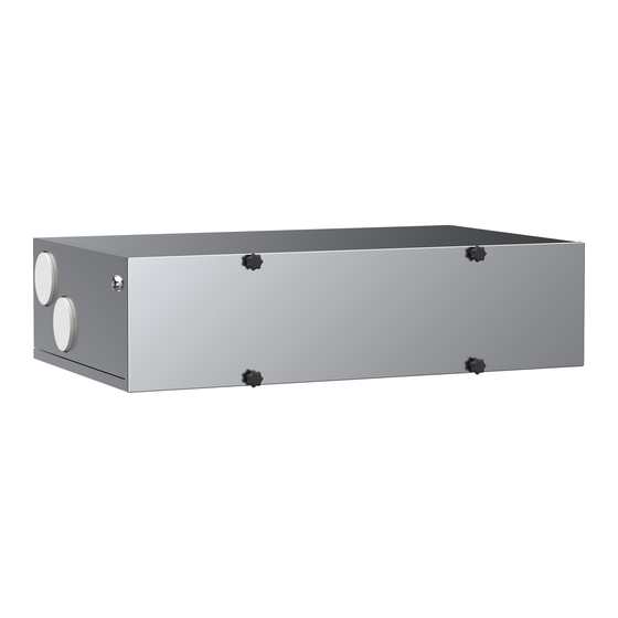
INSTALLATION SITE Vallox TSK Multi 50 MV and Vallox TSK Multi 80 MV must be mounted on the ceiling. Use the mounting hooks (4 pcs) delivered with the unit to mount the ventilation unit on the ceiling. Observe the weight of the unit (45 kg / 58.5 kg) when mounting. - Page 6 DIMENSIONS AND DUCT OUTLETS UNIT DIMENSIONS Dimension Vallox TSK Vallox TSK Multi 50 MV Multi 80 MV 1026 100 (female) 125 (female) R model: L model: Outdoor air to the unit Extract air from the apartment to the unit 2. Supply air from the unit to the apartment 2.
Need help?
Do you have a question about the TSK Multi 50 MV and is the answer not in the manual?
Questions and answers