Table of Contents
Advertisement
Advertisement
Table of Contents

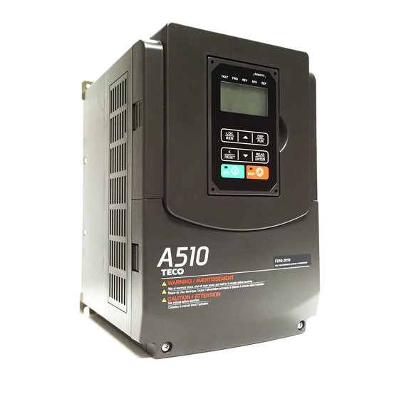
Summary of Contents for TECO-Westinghouse A510
- Page 1 CANopen...
-
Page 2: Table Of Contents
Table of Contents 1.0 CANopen expansion module ......................... 1-0 1.0.1 Communication Hardware and Data Structure ................1-0 1.0.2 Product Specifications ........................1-0 1.0.3 Installation Instructions ......................... 1-1 1.0.4 LED indicator descriptions ......................1-3 1.0.5 Driver Parameter Setting Descriptions ..................1-3 1.0.6 Connection Instructions ........................ -
Page 3: Communication Hardware And Data Structure
1.0 CANopen high speed communication expansion card 1.0.1 Communication hardware and data structure This product is the CANopen high-speed communication expansion module; it can perform remote setting and communication functions through the CANopen bus. It can only be used with the TECO A510s/F510 AC motor driver (hereinafter referred to as the “driver”), and allow the driver to operate on the CANopen network. -
Page 4: Installation Instructions
1.0.3 Installation instructions Communication module contact description As shown in the figure below, A – Terminal block (TB1) B, C – Mounting holes D - RUN LED E - ERR LED F – Control board connector (CN2) Terminal block definition As shown in the figure below, the contact definitions in the order from left to right are GND, CAN_L, NC, CAN_H and NC. - Page 5 ID address setting description As shown in the figure below, ID addresses (1~127) correspond to SW1 b1~b7. Transmission rate corresponds to SW2 b1~b3. DIP switch DIP switch Function status Description position 7654321 0000000 Cannot be used 0000001 Network address is 1 0000010 Network address is 2...
-
Page 6: Led Indicator Descriptions
Network address switch setting range: 1~127 (0, 128~255 cannot be used). Transmission rate switch setting range: 0~7 (8~15 cannot be used). 1.0.4 LED indicator descriptions The module has RUN (green) and ERR (red) indicators built-in used to quickly diagnose and monitor the communication statuses between the module itself and the bus. Module status LED (RUN LED) Used to monitor whether the equipment is operating normally. -
Page 7: Connection Instructions
1.0.6 Connection instructions Service data object (SDO) This module supports 1 SDO server, which means it can provide SDO service, and the SDO uses the sending and receiving COB-ID of the predefined connection, 0x580 + NodeID (sending) and 0x600 + NodeID (receiving). Each SDO message includes a set of COB-ID (request SDO and response SDO);... - Page 8 Write: Slave to master (response code 0x60H) COB-ID Byte0 Byte1 Byte2 Byte3 Byte4 Byte5 Byte6 Byte7 Reque Object index Object Request data (580H) + Node subind Reserved code When we use SDO to perform control to the group 25H of the driver control group, corresponding rules are as follows: Index 25xxH (register...
-
Page 9: Object Index List
R/W Size Remarks 1000H Device type 00010192H 1001H Error register 1005H COB-ID SYNC message 1006H Communication cycle period 1008H Manufacturer device name A510 Manufacturer hardware 1009H version Manufacturer software 100AH 1.00 version 00000080H+Node-I 1014H COB-ID emergency 1015H Inhibit time EMCY... - Page 10 Index Name Default value R/W Size Remarks Number of entries 1.Mapped Object 604F0010H 1601H 2.Mapped Object 60500010H 3.Mapped Object 4.Mapped Object Number of Number of entries entries COB-ID used by PDO 180H+Node-ID Transmission Transmission Type 0xFF type 1800H Inhibit time 0x64 Inhibit time CMS-Priority Group...
- Page 11 DS402 part Sub- Default Index Name R/W Size Unit Index value 603F Error code 6040 Control word 6041 Status word 6042 vl target velocity 6043 vl velocity demand vl ramp function time 604F 0.1S Acceleration time vl slow down time 6050 0.1S Deceleration time...
- Page 12 Monitor DATA (read only) Register Content address 0 Operation status 1: Operate 0: Stop 1 Direction status 1: Reverse 0: Forward Frequency converter operation preparation status 1: Preparation complete 0: Preparation not yet complete 3 Error 1: Abnormal 4 Warning 1: “ON”...
- Page 13 Register Content address 16 DEV 47 Reserved 17 EF1 48 Reserved 18 EF2 49 MtrSw (DI Motor Switch Fault) 19 EF3 50 OCA (Acceleration over-current) OCD (Deceleration over-current) 21 EF5 52 OCC (Operation over-current) 22 EF6 53 CF08 23 EF7 54 PTCLS 24 EF8 55 PF (Protection fault)
- Page 14 25 Reserved 55 BB7 26 Reserved 56 BB8 27 Reserved 57 Reserved 28 Reserved 58 Reserved 29 Reserved 59 Reserved 2529H DO status 252AH 252BH 252CH AI 1 input (0.1%) 252DH AI 2 input (0.1%) 252FH L510(s)/ E510(s)/ A510(s)/ F510 Check 1-11...
-
Page 15: Troubleshooting
1.0.8 Troubleshooting There are two indicators on top of the CANopen communication module; when malfunction occurs, the cause of the malfunction can be confirmed based on the indicator statuses, and troubleshoot the error by following the descriptions below. Indicator troubleshooting Module status LED (RUN LED) Indicator Status name... -
Page 16: Eds File
1.0.9 EDS file When using the CANopen communication module, if the EDS description file (JN5-CMHI-CAN_V (latest version).eds) is needed, please download it from the TECO official website (http://globalsa.teco.com.tw) or TWMC official website (https://www.tecowestinghouse.com/drives-and-controls/ 1-13... -
Page 17: I/O Expansion Card
2.0 I/O expansion card 2.0.1 Hardware and data structure This product is an I/O expansion module; it allows performing of I/O expansion functions through the SPI bus. Used with the TECO A510s/F510 AC motor driver (hereinafter referred to as a driver). 2.0.2 Product specifications I/O ports Item... - Page 18 Ver 02: 2020.01...


Need help?
Do you have a question about the A510 and is the answer not in the manual?
Questions and answers