Table of Contents
Advertisement
R e a d a l l o p e r a t i n g i n s t r u c t i o n s b e f o r e i n s t a l l i n g ,
c o n n e c t i n g ( w i r i n g ) , o p e r a t i n g , s e r v i c i n g , o r i n s p e c t i n g
t h e i n v e r t e r .
E n s u r e t h a t t h i s ma n u a l i s ma d e a v a i l a b l e t o t h e e n d u s e r o f
t h e i n v e r t e r .
S t o r e t h i s ma n u a l i n a s a f e , c o n v e n i e n t l o c a t i o n .
T T h e ma n u a l i s s u b j e c t t o c h a n g e w i t h o u t p r i o r n o t i c e .
L 5 1 0
S T A R T U P MA N U A L
1 1 5 V C l a s s 1 ~
O p e n C h a s s i s
2 3 0 V C l a s s 1 ~ / 3 ~
O p e n C h a s s i s
4 6 0 V C l a s s 3 ~
4 6 0 V
O p e n C h a s s i s
I N V E R T E R
0 . 2 - 0 . 7 5 k W
0 . 2 5 - 1 H P
0 . 2 - 2 . 2 k W
0 . 2 5 - 3 H P
0 . 7 5 - 2 . 2 k W
1 - 3 H P
D O C U ME N T - T E C O - L 5 1 0 S M
V e r 0 1 : 2 0 1 5 . 0 8
Advertisement
Table of Contents

Related Manuals for TECO-Westinghouse L510-1P2-H1-U


Summary of Contents for TECO-Westinghouse L510-1P2-H1-U
- Page 1 I N V E R T E R L 5 1 0 S T A R T U P MA N U A L 1 1 5 V C l a s s 1 ~ O p e n C h a s s i s 0 .
- Page 2 **** STATEMENT **** Si Desea descargar el manual en español diríjase a este Link: www.tecowestinghouse.com Table of Contents Preface .................................... 0-1 1 Safety Precautions (English)............................1-1 1.1 Before Supplying Power to the Inverter ........................1-1 1.2 Wiring ..................................1-2 1.3 Before Operation ................................ 1-3 1.4 Parameters Setting ..............................
- Page 3 4. Keypad and Programming Functions ........................4-1 4.1 LED Keypad ................................4-1 4.1.1 Keypad Display and Keys ..........................4-1 4.1.2 Keypad Menu Structure ............................ 4-3 4.2 Parameters................................. 4-8 5 Troubleshooting and Fault Diagnostics ........................5-1 5.1 General ..................................5-1 5.2 Fault Detection Function ............................5-1 Appendix 1: UL Instructions ............................
-
Page 4: Preface
Preface The L510 product is an inverter designed to control a three-phase induction motor. Please read this manual carefully to ensure correct operation and safety aspects to become familiar with the inverter functions. The L510 inverter is an electrical / electronic product and must be installed and handled by qualified service personnel. -
Page 5: Safety Precautions (English)
1. Safety Precautions (English) 1.1 Before supplying Power to the Inverter Warning The main circuit must be correctly wired. For single phase supply use input terminals (R/L1, T/L3) and for three phase supply use input terminals (R/L1, S/L2, T/L3). Terminals U/T1, V/T2, W/T3 must only be used to connect the motor. -
Page 6: Wiring
1.2 Wiring Warning Always turn OFF the power supply before attempting inverter installation and wiring of the user terminals. Wiring must be performed by a qualified personnel / certified electrician. Make sure the inverter is properly grounded. (230V Class: Grounding impedance shall be less than 100Ω. -
Page 7: Before Operation
1.3 Before Operation Warning Make sure the inverter capacity matches the parameters 13-00. Reduce the carrier frequency (parameter 11-01) If the cable from the inverter to the motor is greater than 80 ft (25m), refer to table 3.14.1. A high-frequency current can be generated by stray capacitance between the cables and result in an overcurrent trip of the inverter, an increase in leakage current, or an inaccurate current readout. -
Page 8: Operation
1.5 Operation Warning Be sure to install all covers before turning on power. Do not remove any of the covers while power to the inverter is on, otherwise electric shock may occur. Do not connect or disconnect the motor during operation. This will cause the inverter to trip and may cause damage to the inverter. -
Page 9: Maintenance, Inspection And Replacement
1.6 Maintenance, Inspection and Replacement Warning Wait a minimum of five minutes after power has been turned OFF before starting an inspection. Also confirm that the charge light is OFF and that the DC bus voltage has dropped below 25Vdc. ... -
Page 10: Consignes De Sécurité (Français)
1. Consignes de sécurité (Français) 1.1 Avant d'alimenter le disque dur Avertissement Le circuit principal doit être correctement câblée. Pour les terminaux monophasés d'approvisionnement de l'utilisation des intrants (R/L1, T/L3) et de trois bornes d'entrée de l'utilisation de l'offre de phase (R/L1, S/L2, T/L3). -
Page 11: Avant L'opération
Attention La tension d'alimentation appliquée doit se conformer à la tension d'entrée spécifiée par le lecteur. (Voir la section signalétique du produit) Raccorder la résistance de freinage et de l'unité de freinage sur les bornes assignées. Ne pas brancher une résistance de freinage directement sur les bornes CC P (+) et N (-), sinon risque d'incendie. -
Page 12: Opération
1.5 Opération Avertissement Veillez à installer tous les couvercles avant de l'allumer. Ne retirez pas les capots pendant que l'alimentation du lecteur est allumé, un choc électrique peut se produire autrement. Ne pas brancher ou débrancher le moteur pendant le fonctionnement. Le variateur pourrai se déclencher et ainsi endommager le lecteur. -
Page 13: Mise Au Rebut Du Variateur
Attention Le variateur peut être utilisé dans un environnement avec une gamme de température allant de 14° -104°F (10-40°C) et l'humidité relative de 95% sans condensation. Le variateur doit être utilisé dans un environnement sans poussière, gaz, vapeur et humidité. 1.7 Mise au rebut du variateur Attention ... -
Page 14: Model Description
2. Model Description 2.1 Nameplate Data It is essential to verify the L510 inverter nameplate and make sure that the L510 inverter has the correct rating so it can be applied with the proper sized AC motor. Unpack the L510 inverter and check the following: (1) The L510 inverter and instruction manual (this document) are contained in the package. -
Page 15: Inverter Models – Motor Power Rating
2.2 Inverter Models – Motor Power Rating (Constant Torque) 115V Class Voltage (Vac) Motor Power Applied Motor & L510 Model (HP) (kW) Frequency (Hz) L510-1P2-H1-U 0.25 100~120V L510-1P5-H1-U +10%/-15% L510-101-H1-U 0.75 50/60Hz 230V Class Voltage (Vac) Motor Power Applied Motor &... -
Page 16: Environment And Installation
3. Environment and Installation 3.1 Environment The environment will directly affect the proper operation and the life span of the inverter. To ensure that the inverter will give maximum service life, please comply with the following environmental conditions: Protection Protection Class IP20, NEMA/UL Open Type Operating Ambient Temperature: (-10°C - +40°C (14 -104 °F) -
Page 17: Installation
3.2 Installation When installing the inverter, ensure that inverter is installed in upright position (vertical direction) and there is adequate space around the unit to allow normal heat dissipation as per the following Fig. 3.2.1 Frame: 1 & 2 CONTROL PANEL Side view Front view... - Page 18 Side by side Installation Provide the necessary physical space and cooling based on the ambient temperature and the heat loss in the panel CONTROL PANEL...
-
Page 19: Mounting On A Flat Surface
3.3 Mounting on a flat surface Frame1: Mounting on a flat surface. Screw: M4 Din rail type installation: Din rail kit includes a plastic and a metal adaptor plate. Assembly Steps: 1) Attach the metal adaptor plate to the inverter base with the screws provided. 2) Attach the plastic Din rail adaptor to the metal adaptor plate. - Page 20 Frame 2: Mounting on a flat surface. Screw: M4 Din rail type installation: Din rail kit includes a plastic adaptor plate as an attachment for the inverter base. Refer to Diagram below: Disassembly:- Assembly:- Plastic Adaptor plate Snap hook Middle Snap hook Din Rail Mounting &...
-
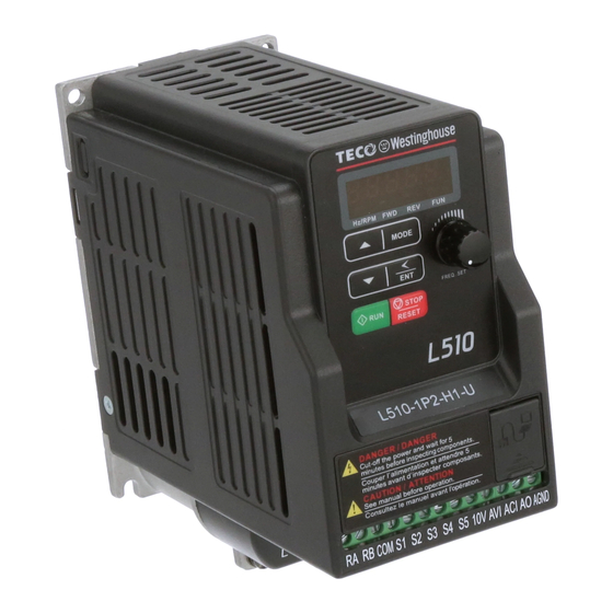
Page 21: Inverter Exterior
3.4 Inverter Exterior Operator panel RS485 Communication Port Ground terminal 3.5 Wire Gauges and Tightening Torque To comply with UL standards, use UL approved copper wires (rated 75° C) and round crimp terminals (UL Listed products) as shown in table below when connecting to the main circuit terminals. TECO recommends using crimp terminals manufactured by NICHIFU Terminal Industry Co., Ltd and the terminal crimping tool recommended by the manufacturer for crimping terminals and the insulating sleeve. -
Page 22: Wiring Peripheral Power Devices
3.6 Wiring Peripheral Power Devices Caution After power is shut off to the inverter the capacitors will slowly discharge. Do NOT touch and of the inverter circuitry or replace any components until the “CHARGE” indicator is off. Do NOT wire or connect/disconnect internal connectors of the inverter when the inverter is powered up or when powered off and the “CHARGE””... - Page 23 Power supply: ~ ~ ~ Power Supply Make sure the correct voltage is applied to avoid damaging the inverter. Molded Molded-case circuit breaker (MCCB) or fused disconnect: Circuit A molded-case circuit breaker or fused disconnect must be installed Breaker between the AC source and the inverter that conforms to the rated voltage and current of the inverter to control the power and protect the...
-
Page 24: General Wiring Diagram
3.7 General Wiring Diagram AC Input Voltage Braking Resistor L1(R) L2(S) L3(T) BR *1 3Ø Induction motor L1/R U/T1 L2/S V/T2 L3/T W/T3 Ground < 100Ω Main Power Section FWD / STOP Analog REV / STOP Output 1 Preset Speed 1 Analog Outputs 0 –... -
Page 25: User Terminals
3.8 User Terminals (Control Circuit Terminals) Terminal symbols TM1 Function Description Relay output terminal, Specification: 250VAC/1A(30VDC/1A) S1~S5 (COMMON) 【NPN】 Multi-function input terminals(refer to group3) Built in Power for an external speed potentiometer Analog voltage input, Specification : 0~10VDC/ 2-10V Analog current input, Specification : 0/4~20mA Multi-function analog output terminal. -
Page 26: Power Terminals
3.9 Power Terminals Terminal symbols TM1 Function Description L1(L) Main power input, L1(L)/L2/L3(N) L3(N) externally connected braking resistor Inverter output, connect to U, V, W terminals of motor Ground terminal *P, BR for 460V series Single phase L1(L) L2 L3(N) Note: Screw for terminal L2 is removed for the single phase models. -
Page 27: Inverter Wiring
3.10 Inverter Wiring Wiring Precautions Do NOT remove any protective covers or attempt any wiring while input power is applied. Connect all wiring before applying input power. When making wiring changes after power up, remove input power and wait a minimum of five minutes after power has been turned off before starting. -
Page 28: Input Power And Motor Cable Length
3.11 Input Power and Motor Cable Length The length of the cables between the input power source and /or the motor and inverter can cause a significant phase to phase voltage reduction due to the voltage drop across the cables. The wire size shown in Tables 3.16.1 is based on a maximum voltage drop of 2%. -
Page 29: Inverter Specifications
3.14 Inverter Specification Basic Specifications 110V class (Single Phase) Model : L510-□□□-H1-U Horse power (HP) 0.25 Suitable motor capacity (KW) 0.75 Rated output current (A) Rated capacity (KVA) 0.68 1.00 1.65 Input voltage range(V) Single Phase : 100~120V,50/60Hz Allowable voltage fluctuation +10%-15% Output voltage range(V) Three phase 0~240V... - Page 30 Basic Specifications 460V class Model : L510-□□□-H3-U Horse power (HP) Suitable motor capacity (KW) 0.75 Rated output current (A) Rated capacity (KVA) Input voltage range(V) Three Phase : 380~480V,50/60Hz Allowable voltage fluctuation +10%-15% Output voltage range(V) Three phase 0~480V Input current (A) Allowable momentary power loss time (S) Enclosure IP20...
-
Page 31: General Specifications
3.15 General Specification Item L510 Control Mode V/F Control + SLV Control Range 0.01~599.00Hz Digital input : 0.01Hz Setting resolution Analog input : 0.06Hz/60Hz Keypad : Set directly with▲▼ keys or use VR (Potentiometer) on the keypad Frequency External Input Terminals: Setting AVI(0/2~10V), ACI(0/4~20mA)input Multifunction input up/down function(Group3) - Page 32 Integrated motor and Inverter overload protection. Overload Protection Over voltage 115V/230V : Over 410V, 460V : Over 820V Under voltage 115V/230V: Under 190V, 460V : Under 380V Momentary Power Loss Inverter auto-restart after a momentary power loss. Restart Stall prevention for Acceleration/ Deceleration/ and continuous Stall Prevention Protective Run.
-
Page 33: Inverter Dimensions
3.17 Inverter Dimensions Frame 1: Unit : Inch (mm) Model Weight L510-1P2-H1-U L510-1P5-H1-U L510-2P2-H1-U L510-2P5-H1-U 2.83 2.48 2.40 5.55 5.16 (4.80) (5.57) (5.35) 1.98 lbs. (72) (63) (61) (141) (131) (0.9kg) L510-201-H1-U L510-2P2-H3-U L510-2P5-H3-U L510-201-H3-U 3-18... - Page 34 Frame 2: Unit : Inch (mm) Model Weight L510-101-H1-U L510-202-H1-U L510-203-H1-U L510-202-H3-U 4.65 4.25 4.25 5.67 5.16 4.76 5.92 5.68 3.53 Lbs. (118) (108) (108) (144) (131) (121) (150) (144) (1.6kg) L510-203-H3-U L510-401-H3-U L510-402-H3-U L510-403-H3-U 3-19...
-
Page 35: Keypad And Programming Functions
4. Keypad and Programming Functions 4.1 LED Keypad 4.1.1 Keypad Display and Keys LED Display Forward Direction Reverse Direction Status Indicator Status Indicator Frequency Potentiometer 6 button Membrane Keypad Run Key Stop Key DISPLAY Description 5 Digit LED Display Monitor inverter signals, view / edit parameters, fault / alarm display. LED INDICATORS Hz/RPM LED ON when frequency or line speed is displayed. - Page 36 4.1.2 Digital display Description Actual LED Display Actual LED Display Actual LED Display Actual LED Display ° Display output frequency Frequency Reference Set Frequency Reference LED lights on LED flashes Flashing digit At power-up the display will show the frequency reference setting, all LEDs are flashing. Press the ▲UP or ▼DOWN key to enter the frequency reference edit mode, use the ◄/ENT key to select which digit to edit (flashing).
- Page 37 LED display examples Seven Segment display Description 1. Displays the frequency reference at power-up 2. Display the actual output frequency in operation status. Display parameter code Display the setting value of parameter Display input voltage Display inverter current. Display DC Bus Voltage Display temperature Display PID feedback value.
- Page 38 4.1.3 LED Status description Hz/ RPM LED State Description Hz/RPM LED Display doesn’t show frequency or line speed Illuminated Display shows frequency or line speed Forward LED State Description FWD LED Inverter in reverse direction Illuminated Inverter is running in forward direction Flashing Forward direction active, no run command Reverse LED...
- Page 39 4.1.4 Power-Up Monitor Power Up: MODE MODE After 2 sec. Display at Power-up Frequency Reference Parameter Selection Change Monitor at Power-Up 12-00 Display selection Highest bit -> 0 0 0 0 0 <- Lowest bit The setting range for each bit is 0 ~ 7 from the highest bit to the lowest bit. Range 0: No display 4: Temperature...
- Page 40 Example: 12-00 = 12345 MODE Heatsink Temperature <4> MODE MODE DC Voltage <3> Output Voltage <2> PID Feedback <5> MODE MODE After 2 sec. Display Voltage Class Output Current <1> Parameter Selection at Power-up MODE MODE Frequency Reference 4.1.5 Modifying Parameters / Set Frequency Reference Frequency Short Press: Mode Once...
- Page 41 4.1.6 Operation Control Stopped Running Stopping Stopped Output Frequency Indicator Indicator...
-
Page 42: Parameters
4.2 Parameters Parameter group Name Group 00 Basic Parameters Group 01 V/F Control Parameters Group 02 Motor Parameters Group 03 External Digital Input and Output Parameters Group 04 External Analog Input and Output Parameters Group 05 Multi-Speed Parameters Group 06 Automatic Program Operation Parameters Group 07 Start /Stop Parameters... - Page 43 Group 00: Basic Parameters Code Parameter Name Setting Range Default Unit Note 0: V/F mode 00-00 Control Method 1: SLV mode 0: Forward 00-01 Motor Rotation 1: Reverse 0: Keypad 00-02 Main Run Source Selection 1: External Run/Stop 2: Communication 0: Keypad 00-03 Alternative Run Source Selection...
- Page 44 Group 00: Basic Parameters Code Parameter Name Setting Range Default Unit Note 00-19 Jog Acceleration Time 0.1~25.5 00-20 Jog Deceleration Time 0.1~25.5 Group 01: V/F Control Parameters Code Parameter Name Setting Range Default Unit Notes 01-00 Volts/Hz Patterns 220.0/38 01-01 V/F Max voltage 200V:170.0~264.0 400V:323.0~528.0...
- Page 45 Group 02: Motor Parameters SLV Slip 02-13 0~150 by series Compensation Gain 02-14 0~100 SLV Torque Compensation Gain 02-15 0~100 Low Frequency Torque Gain SLV Without Load Slip 02-16 0~200 by series Compensation Gain SLV With Load Slip Compensation 02-17 0~200 Gain Group 03: External Digital Input and Output Parameters...
- Page 46 Group 03: External Digital Input and Output Parameters Code Parameter Name Setting Range Default Unit Notes 7:Momentary AC Power Loss 8:Rapid Stop 9:Base Block 10:Motor Overload Protection(OL1) 11:Drive Overload Protection(OL2) 12:Reserved 13:Output Current Reached 14:Brake Control 15:PID feedback disconnection detection 03-12 Reserved 03-13...
- Page 47 Group 04: External Analog Input and Output Parameters Code Parameter Name Setting Range Default Unit Notes 1: Negative 0: Output Frequency 1: Frequency Command 04-11 Analog Output mode(AO) 2: Output Voltage 3: DC Bus Voltage 4: Motor Current 0 ~ 1000 04-12 Analog Output AO Gain (%) 0 ~ 100...
- Page 48 Group 05: Multi-Speed Function Group Code Parameter Name Setting Range Default Unit Notes Preset Speed7-Acctime 05-31 0.1 ~ 3600.0 10.0 Preset Speed7-Dectime 05-32 0.1 ~ 3600.0 10.0 Group 06: Automatic Program Operation Parameters Code Parameter Name Setting Range Default Unit Notes 0: Disabled 1: Single cycle.
- Page 49 Group 06: Automatic Program Operation Parameters Code Parameter Name Setting Range Default Unit Notes 06-31 Auto_ Run Mode running direction 2 06-32 0: Stop Auto_ Run Mode running direction 3 06-33 Auto_ Run Mode running direction 4 06-34 1: Forward Auto_ Run Mode running direction 5 06-35 Auto_ Run Mode running direction 6...
- Page 50 Group 08: Protection Parameters Code Parameter Name Setting Range Default Unit Notes x1xxx: Disable over voltage Prevention in Run Mode Trip Prevention Level 08-01 50 ~ 200 by series During Acceleration (%) Trip Prevention Level 08-02 50 ~ 200 by series During Deceleration (%) Trip Prevention Level In 08-03...
- Page 51 Group 08: Protection Parameters Code Parameter Name Setting Range Default Unit Notes 08-12 PTC Detection Time Delay 1~300 08-13 PTC Protection Level 0.1~10.0 08-14 PTC Detection Level Reset 0.1~10.0 08-15 PTC Warning Level 0.1~10.0 08-16 Fan Control Temperature Level 10.0~50.0 50.0 °C Group 09: Communication Parameters...
- Page 52 Group 10: PID Parameters Code Parameter Name Setting Range Default Unit Notes ,this function is enabled) 2: Analog Signal Input (ACI) 3: Freq. set by Communication 4: Keypad Freq. Parameter 10-02 0: Potentiometer on Keypad 1: Analog Signal Input (AVI) PID feedback value selection 10-01 2: Analog Signal Input (ACI)
- Page 53 Group 10: PID Parameters Code Parameter Name Setting Range Default Unit Notes 0 ~999 10-21 Max PID Feedback Setting 0 ~999 10-22 Min PID Feedback Setting Group 11: Auxiliary Parameters Code Parameter Name Setting Range Default Unit Notes 0: Reverse command is enabled 11-00 Reverse operation control 1: Reverse command is disabled...
- Page 54 Group12: Monitoring Parameters Code Parameter Name Setting Range Default Unit Notes 7:Analog Signal Input. (ACI) 0: Integer (xxx) 12-01 PID Feedback Display format 1:One decimal Place (xx.x) 2:Two Decimal Places (x.xx) 0:xxx-- PID Feedback Display Unit 12-02 1:xxxpb (pressure) Setting 2:xxxfl (flow) 12-03 0~65535...
- Page 55 Group 13: Maintenance Parameters Code Parameter Name Setting Range Default Unit Notes 13-00 ---- Drive Horsepower Code 13-01 ---- *3*4 Software Version Fault Log 13-02 ---- *3*4 (Last 3 Faults) Accumulated Operation 13-03 0~23 hour Time1 1 Accumulated Operation 13-04 0~65535 ---- Time1 2...
-
Page 56: Troubleshooting And Fault Diagnostics
5. Troubleshooting and Fault Diagnostics 5.1 General Inverter fault detection and early warning / self-diagnosis function. When the inverter detects a fault, a fault message is displayed on the keypad. When the inverter detects a warning / self-diagnostics error, the digital operator will display a warning or self-diagnostic code, the fault output does not energize in this case. - Page 57 LED display Description Cause Possible solutions DC bus voltage is Under voltage lower than the UV detection level or the pre-charge The input voltage is too low. Check the input voltage. contactor is not Input phase loss. ...
- Page 58 Disconnect motor and try greater than the inverter rated value. overcurrent level running inverter. Short circuit or ground fault. (200% of the inverter rated current). OC-C The inverter output over current at Acceleration / Deceleration time is too short. ...
- Page 59 LED display Description Cause Possible solutions Inverter over current: Wait 1 minute to Check motor load and operating reset .If it occurs CL Inverter over current warning: Inverter current or OL2 up to 4 time.. reached over current protection level. successive times then wait 5 minutes to reset...
- Page 60 LED display Description Cause Possible solutions 1.Parameter locked already locked Attempt to modify frequency parameter while 2.Motor direction 13-06>0. Adjust 13-06 Attempt to reverse direction when 11-00=1 locked Adjust 11-00 Parameter (13 - 07) enabled, set the correct 3.Parameter password will show LOC.
- Page 61 LED display Fault Description StP0 Zero speed at stop Occurs when preset frequency <0.1Hz If the inverter is set for external terminal control mode (00-02/00-03=1) and StP1 Fail to start directly direct start is disabled (07-04=1) The inverter cannot be started and will flash STP1. On power up.
- Page 62 Appendix 1: UL Instructions Danger Electric Shock Hazard Do not connect or disconnect wiring while the power is on. Failure to comply will result in death or serious injury. Warning Electric Shock Hazard Do not operate equipment with covers removed. Failure to comply could result in death or serious injury.
- Page 63 Warning Fire Hazard Tighten all terminal screws to the specified tightening torque. Loose electrical connections could result in death or serious injury by fire due to overheating of electrical connections. Do not use an improper voltage source. Failure to comply could result in death or serious injury by fire. Verify that the rated voltage of the inverter matches the voltage of the incoming power supply before applying power.
- Page 64 UL Standards The UL/cUL mark applies to products in the United States and Canada and it means that UL has performed product testing and evaluation and determined that their stringent standards for product safety have been met. For a product to receive UL certification, all components inside that product must also receive UL certification.
- Page 65 Main Circuit Terminal Wiring UL approval requires crimp terminals when wiring the inverter’s main circuit terminals. Use crimping tools as specified by the crimp terminal manufacturer. TECO recommends crimp terminals made by NICHIFU for the insulation cap. The table below matches inverter models with crimp terminals and insulation caps. Orders can be placed with a TECO representative or directly with the TECO sales department.
- Page 66 Recommended Input Fuse Selection Fuse Type Drive Model L510 Manufacturer: Bussmann Model Fuse Ampere Rating (A) 100 V Class Single-Phase Drives Bussmann 16CT 690V 16A Bussmann 20CT 690V 20A Bussmann 25ET 690V 25A Fuse Type Drive Model L510 Manufacturer: Bussmann Model Fuse Ampere Rating (A) 200 V Class Single-Phase Drives...
- Page 67 Motor Over Temperature Protection Motor over temperature protection shall be provided in the end use application. ■ Field Wiring Terminals All input and output field wiring terminals not located within the motor circuit shall be marked to indicate the proper connections that are to be made to each terminal and indicate that copper conductors, rated 75°C are to be used.
- Page 68 ■ 08-05 Motor Overload Protection Selection The inverter has an electronic overload protection function (OL1) based on time, output current, and output frequency, which protects the motor from overheating. The electronic thermal overload function is UL-recognized, so it does not require an external thermal overload relay for single motor operation. This parameter selects the motor overload curve used according to the type of motor applied.
Need help?
Do you have a question about the L510-1P2-H1-U and is the answer not in the manual?
Questions and answers