Table of Contents
Advertisement
Quick Links
R e a d a l l o p e r a t i n g i n s t r u c t i o n s b e f o r e i n s t a l l i n g ,
c o n n e c t i n g ( w i r i n g ) , o p e r a t i n g , s e r v i c i n g , o r i n s p e c t i n g
t h e i n v e r t e r .
E n s u r e t h a t t h i s ma n u a l i s ma d e a v a i l a b l e t o t h e e n d u s e r o f
t h e i n v e r t e r .
S t o r e t h i s ma n u a l i n a s a f e , c o n v e n i e n t l o c a t i o n .
T T h e ma n u a l i s s u b j e c t t o c h a n g e w i t h o u t p r i o r n o t i c e .
R e f e r t o t h e E 5 1 0 I n s t r u c t i o n Ma n u a l ( www . t e c o w e s t i n g h o u s e . c o m) .
I N V E R T E R
E 5 1 0
S T A R T - U P A N D I N S T A L L A T I O N MA N U A L
2 3 0 V C l a s s 1 / 3 ~
I P 2 0 / N E M A 1
0 . 4 - 2 . 2 k W / 0 . 5 - 3 H P
2 3 0 V C l a s s 3 ~
I P 2 0 / N E M A 1
0 . 4 - 3 0 k W / 0 . 5 - 4 0 H P
4 6 0 V C l a s s 3 ~
4 6 0 V
I P 2 0 / N E M A 1
0 . 7 5 - 5 5 k W / 1 - 7 5 H P
D O C U ME N T - T E C O - E 5 1 0 N 1 S I
V e r 0 1 : 2 0 1 7 . 1 1
Advertisement
Table of Contents
Troubleshooting

Related Manuals for TECO-Westinghouse E510-201-H-U


Summary of Contents for TECO-Westinghouse E510-201-H-U
- Page 1 I N V E R T E R E 5 1 0 S T A R T - U P A N D I N S T A L L A T I O N MA N U A L 2 3 0 V C l a s s 1 / 3 ~ I P 2 0 / N E M A 1 0 .
-
Page 2: Table Of Contents
**** STATEMENT **** Si Desea descargar el manual en español diríjase a este Link: www.tecowestinghouse.com Table of Contents Preface (English) ............................0-1 Preface (Français) ............................0-2 1 Safety Precautions (English) ........................1-1 1.1 Before Supplying Power to the Inverter ....................1-1 1.2 Wiring ................................ - Page 3 3.3 External View ............................3-3 3.4 Warning Labels ............................3-6 3.5 Removing the Front Cover ........................3-7 3.6 Wire Gauges, Tightening Torque, Short Circuit, Circuit Breaker and Fuse Ratings....... 3-14 3.7 Wiring Peripheral Power Devices ......................3-16 3.8 General Wiring Diagram .......................... 3-18 3.9 User Terminals ............................
- Page 4 7. Operation Method Configuration (Run / Stop) ..................7-1 7.1 Run / Stop from the Keypad ........................7-1 7.2 Run / Stop from External Switch / Contact or Pushbutton ................ 7-2 7.3 Run / Stop from Serial Communication RS485 ..................7-4 8.
-
Page 5: Preface (English)
Preface (English) The E510 product is an inverter designed to control a three-phase induction motor. Please read this manual carefully to ensure correct operation, safety and to become familiar with the inverter functions. The E510 inverter is an electrical / electronic product and must be installed and handled by qualified service personnel. -
Page 6: Preface (Français)
Préface (Français) Le produit est un lecteur conçu pour commander un moteur à induction triphasé. lire attentivement ce manuel pour garantir le bon fonctionnement, la sécurité et pour se familiariser avec les fonctions d'entraînement. Le lecteur est un appareil électrique / électronique et doit être installé et géré par un personnel qualifié ... -
Page 7: Safety Precautions (English)
1. Safety Precautions (English) 1.1 Before supplying Power to the Inverter Warning The main circuit must be correctly wired. For single phase supply use input terminals (R/L1, T/L3) and for three phase supply use input terminals (L1(L), L2, L3(N)). Terminals T1, T2, T3 must only be used to connect the motor. -
Page 8: Wiring
1.2 Wiring Warning Always turn OFF the power supply before attempting inverter installation and wiring of the user terminals. Wiring must be performed by a qualified personnel / certified electrician. Make sure the inverter is properly grounded. (230V Class: Grounding impedance shall be less than 100Ω. -
Page 9: Before Operation
1.3 Before Operation Warning Make sure the inverter capacity matches the parameters 13-00. Reduce the carrier frequency (parameter 11-01) If the cable from the inverter to the motor is greater than 80 ft (25m). A high-frequency current can be generated by stray capacitance between the cables and result in an overcurrent trip of the inverter, an increase in leakage current, or an inaccurate current readout. -
Page 10: Operation
1.5 Operation Warning Be sure to install all covers before turning on power. Do not remove any of the covers while power to the inverter is on, otherwise electric shock may occur. Do not connect or disconnect the motor during operation. This will cause the inverter to trip and may cause damage to the inverter. -
Page 11: Maintenance, Inspection And Replacement
1.6 Maintenance, Inspection and Replacement Warning Wait a minimum of five minutes after power has been turned OFF before starting an inspection. Also confirm that the charge light is OFF and that the DC bus voltage has dropped below 25Vdc. ... -
Page 12: Consignes De Sécurité (Français)
1. Consignes de sécurité (Français) 1.1 Avant d'alimenter le disque dur Avertissement Le circuit principal doit être correctement câblée. Pour les terminaux monophasés d'approvisionnement de l'utilisation des intrants (R/L1, T/L3) et de trois bornes d'entrée de l'utilisation de l'offre de phase (R/L1, S/L2, T/L3). -
Page 13: Avant L'opération
Attention La tension d'alimentation appliquée doit se conformer à la tension d'entrée spécifiée par le lecteur. (Voir la section signalétique du produit) Raccorder la résistance de freinage et de l'unité de freinage sur les bornes assignées. Ne pas brancher une résistance de freinage directement sur les bornes CC P (+) et N (-), sinon risque d'incendie. -
Page 14: Opération
1.5 Opération Avertissement Veillez à installer tous les couvercles avant de l'allumer. Ne retirez pas les capots pendant que l'alimentation du lecteur est allumé, un choc électrique peut se produire autrement. Ne pas brancher ou débrancher le moteur pendant le fonctionnement. Le variateur pourrai se déclencher et ainsi endommager le lecteur. -
Page 15: Mise Au Rebut Du Variateur
Attention Le variateur peut être utilisé dans un environnement avec une gamme de température allant de 14 ° -104 ° F (10-40 ° C) et l'humidité relative de 95% sans condensation. Le variateur doit être utilisé dans un environnement sans poussière, gaz, vapeur et humidité. 1.7 Mise au rebut du variateur Attention ... -
Page 16: Model Description
2. Model Description 2.1 Nameplate Data It is essential to verify the E510 inverter nameplate and make sure that the E510 inverter has the correct rating so it can be used in your application with the proper sized AC motor. Unpack the E510 inverter and check the following: (1) The E510 inverter start-up and installation manual (this document) are contained in the package. -
Page 17: Inverter Models - Motor Power Rating
Horse Motor Frame Filter Function Model voltage Power (kW) Size (Vac) (HP) ◎ ◎ E510-2P5-H-U 1 Phase ◎ ◎ E510-201-H-U 0.75 200~240V +10%-15% ◎ ◎ E510-202-H-U 50/60Hz ◎ ◎ E510-203-H-U ◎ ◎ E510-2P5-H1F-U* 1 & 3 Phase ◎ ◎ E510-201-H1F-U* 0.75... - Page 18 IP20 / NEMA 1 Type – 400V Class Supply Horse STO Function Motor Frame Filter Model voltage Power (kW) Size (Vac) (HP) ◎ ◎ E510-401-H3-U 0.75 ◎ ◎ E510-402-H3-U ◎ ◎ E510-403-H3-U ◎ ◎ E510-405-H3-U ◎ ◎ E510-408-H3-U ◎ ◎ E510-410-H3-U ◎...
-
Page 19: Environment And Installation
3. Environment and Installation 3.1 Environment The environment will directly affect the proper operation and the life span of the inverter. To ensure that the inverter will give maximum service life, please comply with the following environmental conditions: Protection Protection Class IP20 / NEMA 1 (Depending on models) Operating IP20 / NEMA 1 type:... -
Page 20: Installation
3.2 Installation Provide sufficient air circulation space for cooling as shown in examples below. Install the Inverter on surfaces that provide good heat dissipation. Frame1 models:2P5 / 201 / 202 (three phase) / 401 / 402. Inside Inside Enclosure Enclosure 4.8”... -
Page 21: External View
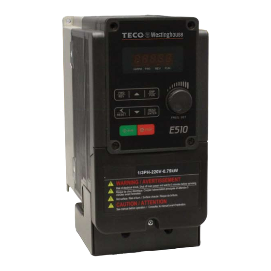
3.3 External View IP20 200V 0.5HP~1HP (Single/Three phase) / 400V 1HP~2HP / 200V 2HP (Three phase) Mounting hole Heat sink Digital operator Name plate label Fan cover Terminal cover NEMA1 200V 0.5HP~1HP (Single/Three phase) / 400V 1HP~2HP / 200V 2HP (Three phase) Mounting hole Heat sink Digital operator... - Page 22 IP20 200V 2-3HP (Single/Three phase) / 200V 3HP~20HP / 400V 3HP~25HP Mounting hole Heat sink Digital operator Name plate label Terminal cover Fan cover NEMA1 200V 2-3HP (Single/Three phase) / 200V 3HP~20HP / 400V 3HP~25HP Mounting hole Digital operator Heat sink Name plate label Terminal cover Fan cover...
- Page 23 NEMA 1 200V 25HP / 400V 30HP Anti-dust cover Mounting hole Front cover Digital operator Name plate label Terminal cover NEMA 1 200V 30HP~40HP / 400V 40HP~75HP Front cover Mounting hole Digital operator Rings(4 rings) Terminal cover Name plate label...
-
Page 24: Warning Labels
3.4 Warning Labels Important: Warning information located on the front cover must be read upon installation of the inverter. (a) 200V 0.5HP~20HP / 400V 1HP~25HP (b) 200V 25HP~40HP / 400V 30HP~75HP... -
Page 25: Removing The
3.5 Removing the Front Cover Caution Before making any wiring connections to the inverter the front cover needs to be removed. IP20 200V 0.5HP~1HP (Single/Three phase)/ 400V 1HP~2HP / 200V 2HP (Three phase) Step1:Remove terminal cover Step2:Wire and reinstall cover Step3:Put terminal cover back... - Page 26 NEMA 1 200V 0.5HP~1HP (Single/Three phase)/ 400V 1HP~2HP / 200V 2HP (Three phase) Step1:Remove terminal cover Step2:Wire and reinstall cover Step3:Put terminal cover back...
- Page 27 IP20 200V 2HP (single/three phase) / 200V 3HP~20HP / 400V 3HP~25HP Step1:Unscrew cover Step2:Remove the terminal cover Step3:Wire and reinstall the cover Step4:Tighten the screws...
- Page 28 NEMA1 200V 2HP (single/three phase) / 200V 3HP~20HP / 400V 3HP~25HP Step1:Unscrew cover Step2:Remove the terminal cover Step3:Wire and reinstall the cover Step4:Tighten the screws 3-10...
- Page 29 NEMA1 200V 25HP / 400V 30HP Step1: Unscrew cover Step2: Remove the terminal cover Step3:Wire and reinstall the cover Step4:Tighten the screws 3-11...
- Page 30 NEMA1 200V 30HP~40HP / 400V 40HP~75HP Step1: Unscrew cover Step2: Remove the terminal cover Step3:Wire and Reinstall the cover Step4:Tighten the screws 3-12...
- Page 31 NEMA1 400V 20HP~75HP (with EMC filter) Step1: Unscrew cover Step2: Remove the terminal cover Step3:Wire and reinstall the cover Step4:Tighten the screws 3-13...
- Page 32 3.6 Wire Gauges, Tightening Torque, Terminal , Short Circuit, Circuit Breaker and Fuse Ratings Wire Gauges Tightening Torque Frame Power Input wiring Output wiring Voltage Amps size specification (TM1) (TM1) kgf.cm lbf.in 14 AWG 14 AWG 200V~240V 0.5/1 (2.5 mm²) (2.5 mm²) Frame1 0.96...
- Page 33 Terminals Electrical Rating Model Horsepower Power Specification Voltage (Volt) Current(A) 0.5/1 200V~240V Frame1 380V~480V 2/3/5 200V~240V Frame2 380V~480V 7.5/10/15/20 200V~240V Frame 3/4 7.5/10/15/20/25 380V~480V 200V~240V Frame 5 380V~480V 30/40 200V~240V Frame 6 40/50/60/75 380V~480V Short circuit rating Device Rating Short circuit Maximum Rating (A) Voltage (Volt)
-
Page 34: Wiring Peripheral Power Devices
3.7 Wiring Peripheral Power Devices Caution After power is shut off to the inverter the capacitors will slowly discharge. Do NOT touch and of the inverter circuitry or replace any components until the “CHARGE” indicator is off. Do NOT wire or connect/disconnect internal connectors of the inverter when the inverter is powered up or when powered off and the “CHARGE””... - Page 35 ~ ~ ~ Power supply: Power Supply Make sure the correct voltage is applied to avoid damaging the inverter. Molded Molded-case circuit breaker (MCCB) or fused disconnect: Circuit A molded-case circuit breaker or fused disconnect must be installed Breaker between the AC source and the inverter that conforms to the rated voltage and current of the inverter to control the power and protect the...
-
Page 36: General Wiring Diagram
3.8 General Wiring Diagram AC Input Voltage Braking Resistor L1(R) L2(S) L3(T) 3Ø Induction motor L1(L) L3(N) Ground < 100Ω RS485 FWD / STOP CON 2 1:Data+ REV / STOP 2:Data- 3:Data+ Preset Speed 1 4:RXD0 5:TXD0 Multi- Preset Speed 2 6:Data- Functional Digital Input... - Page 37 3.9 User Terminals (Control Circuit Terminals) AGND S(+) S(-) Jumper function descriptions Jumper Symbol Funct ion Si gn al R ef er en c e Note NPN Input J P 1 NPN/PNP selectable Factory default setting PNP Input 0~20mA / 4~20mA Set parameters Analog signal External signal type...
-
Page 38: User Terminals
Description of User Terminals Type Terminal Terminal function Signal level 24 VDC, 8 mA, Optical coupling isolation (Max, Digital Refer to parameter group 3 for more information and default voltage 30 VDC, Input impedance 3.3kΩ) inputs settings. High Logic: 13V Low Logic: 10V NO(Normally open) - Page 39 Notes: *1:Multi-function digital input can be referred to in this manual. - Group 03: External Terminals Digital Input / Output Function Group. *2:Multi-function analog input can be referred to in this manual. - Group 04 - External Terminal Analog Signal Input (Output) Function Group. *3:Multi-function analog output can be referred to in this manual.
-
Page 40: Power Terminals
3.10 Power Terminals Terminal symbol TM1 function description Single phase: L1(L) L1(L)/L3(N) Single/Three phase: Main power input, L1(L)/L2/L3(N) Three phase: L3(N) L1/L2/L3 Inverter output, connect to U/V/W terminals of motor Externally connected braking resistor (Please see the braking resistors reference on section 11.2) Ground terminal Main power terminal of Single phase 200V Class 0.5~1HP L1(L) - Page 41 Main power terminal of Single/Three phase 200V Class 2~3HP L1(L) L2 L3(N) P Main power terminal of Single/Three phase 200V Class 2~3HP, Three phase 200V Class 5HP and Three phase 400V Class 3~5HP L1(L) L2 L3(N) P Main power terminal of Three phase 200V Class 7.5~20HP and Three phase 400V Class 7.5~20HP L1(L) L2 L3(N) P Main power terminal of Three phase 200V Class 25HP and Three phase 400V Class 30HP...
- Page 42 Main power terminal of Three phase 200V Class 30~40HP and Three phase 400V Class 40~75HP R/L1 S/L2 T/L3 U/T1 V/T2 W/T3 3-24...
-
Page 43: Inverter Wiring
3.11 Inverter Wiring Wiring Precautions Do NOT remove any protective covers or attempt any wiring while input power is applied. Connect all wiring before applying input power. When making wiring changes after power up, remove input power and wait a minimum of five minutes after power has been turned off before starting. - Page 44 (B) Grounding Connect the ground terminal (E) to ground having a resistance of less than 100Ω. Do not share the ground wire with other devices, such as welding machines or power tools. Always use a ground wire that complies with the local codes and standards for electrical equipment and minimize the length of ground wire.
-
Page 45: Input Power And Motor Cable Length
3.12 Input Power and Motor Cable Length The length of the cables between the input power source and /or the motor and inverter can cause a significant phase to phase voltage reduction due to the voltage drop across the cables. The wire size shown in Tables 3.13.1 is based on a maximum voltage drop of 2%. -
Page 46: Power Input Wire Size And Nfb
3.15 Power Input Wire Size, and NFB The following table shows the recommended wire size for each frame of the E510. It depends on the application whether or not to install a circuit breaker. The NFB must be installed between the input power supply and the inverter input (L1 (L), L2, L3 (N)). -
Page 47: Inverter Specifications
3.17 Inverter Specification 200V Class:Single phase Model:E510-□□□-H1F-U* Horse power (HP) Suitable motor capacity (KW) 0.75 Rated output current (A) 10.5 Rated capacity (KVA) 2.90 4.00 Single phase:200~240V, 50/60HZ Input voltage range(V) Allowable voltage fluctuation -15%~+10% Three phase:0~240V Output voltage range(V) Input current (A)* 23.9 Inverter net weight (KG) - Page 48 200V Class:Three phase Model:E510-□□□-H3-U Horse power (HP) Suitable motor capacity (KW) Rated output current (A) 17.5 Rated capacity (KVA) 13.3 20.6 27.4 Three phase:200~240V,50/60HZ Input voltage range(V) Allowable voltage fluctuation -15%~+10% Three phase:0~240V Output voltage range(V) Input current (A)* 20.5 Inverter net weight (KG) 10.1 10.4...
- Page 49 400V Class:Three phase Model:E510-□□□-H3(F*)-U Horse power (HP) Suitable motor capacity (KW) 0.75 Rated output current (A) Rated capacity (KVA) Three phase:380~480V,50/60HZ Input voltage range(V) Allowable voltage fluctuation -15%~+10% Three phase:0~480V Output voltage range(V) Input current (A)* 11.6 Inverter net weight (KG) Allowable momentary power loss time(s) Enclosure IP20/NEMA1...
- Page 50 400V Class:Three phase Model:E510-□□□- H3(F*)-U Horse power (HP) HD/ND Suitable motor capacity (kW) 22/30 30/37 HD/ND Rated output current (A) 45/58 60/73 HD/ND Rated capacity (KVA) 34.3/44.2 45.7/55.6 Input voltage range(V) Three phase : 380~480V,50/60HZ Allowable voltage fluctuation +10%-15% Output voltage range(V) Three phase : 0~480V Input current (A)* 48.9/63...
-
Page 51: General Specifications
3.18 General Specification Item E510 Control Mode V/F, SLV, PMSLV control mode 0.01~599.00Hz Output Frequency 150% / 1Hz (SLV mode),150% / 3Hz (V/F mode) Starting Torque Speed Control Range 1:50 Digital input: 0.01Hz Setting resolution Analog input:0.06Hz/60Hz Frequency Keypad: Set directly with▲▼ keys or the VR on the keypad External Input Terminals: AI1(0/2~10V), AI2(0/4~20mA)input Setting... - Page 52 Grounding Fault Electronic Circuit Protection Protection for overheating of heat sink, The carrier frequency decreases based on the temperature, Fault output, Reverse Other protection features prohibit, Prohibit for direct start after power up and error recovery ,parameter lock up, STO (Safety Torque Off) All frames include brake transistor Built-in RS485 communication multi-drop communication.
-
Page 53: Inverter Derating Based On Carrier Frequency
3.19 Inverter derating based on Carrier Frequency The curves are showing the applicable output current de-rate due to setting of carrier frequency and the ambient operating temperatures of 40 and 50 degrees. When the carrier frequency is below 10 KHz ambient temperature will not affect rated current. When the carrier frequency is higher than 10 KHz If the ambient temperature is below 40°C (104°F), 100% output rated current at 16 KHz. -
Page 54: Inverter Dimensions
Inverter Model kg/(lbs) 151.4 90.6 80.5 80.5 E510-2P5-H-U 1.6/(3.5) (5.96) (3.57) (3.17) (3.17) (6.46) (6.02) (1.85) (0.19) 151.4 90.6 80.5 80.5 E510-201-H-U 1.6/(3.5) (5.96) (3.57) (3.17) (3.17) (6.46) (6.02) (1.85) (0.19) 151.4 90.6 80.5 80.5 E510-2P5-H1F-U 1.7/(3.8) (5.96) (3.57) (3.17) (3.17) (6.46) - Page 55 200V Class single/three phase:2HP 400V Class three phase:3~25HP 200V Class three phase:3~20HP Net Weight Dimensions in mm (inch) Inverter Model Kg/(lbs) 128.7 187.6 177.6 197.5 152.4 147.4 48.2 2.5/(5.5) E510-202-H-U (5.07) (4.65) (4.65) (7.39) (6.99) (7.78) (5.8) (1.9) (0.19) 128.7 187.6 177.6 197.5...
- Page 56 Net Weight Dimensions in mm (inch) Inverter Model Kg/(lbs) 197.6 186.9 260.9 249.8 76.7 202.6 E510-415-H3-U 6.5/(14.3) (7.98) (7.78) (7.36) (6.89) (6.93) (10.27) (9.83) (10.75) (3.02) (0.26) 197.6 186.9 260.9 249.8 76.7 202.6 E510-408-H3F-U 6.7/(14.8) (7.98) (7.78) (7.36) (6.89) (6.93) (10.27) (9.83) (10.75)
- Page 57 200V Class three phase:25HP 400V Class three phase:30HP Net Weight Dimensions in mm (inch) Inverter Model Kg/(lbs) 233.2 238.2 E510-225-H3-U 10/(22.1) (9.38) (9.18) (10.43) (9.65) (9.65) (14.17) (13.39) (0.06) 233.2 238.2 E510-430-H3-U 10/(22.1) (9.38) (9.18) (10.43) (9.65) (9.65) (14.17) (13.39) (0.06) 3-39...
- Page 58 200V Class three phase:30~40HP 400V Class three phase:40~75HP Net Weight Dimensions in mm (inch) Inverter Model Kg/(lbs) 269.8 286.5 E510-230-H3-U 30/(66.1) (10.62) (11.28) (8.66) (8.66) (20.67) (19.88) (0.13) 269.8 286.5 E510-240-H3-U 30/(66.1) (10.62) (11.28) (8.66) (8.66) (20.67) (19.88) (0.13) 269.8 286.5 E510-440-H3-U 30/(66.1)
- Page 59 186.2 189.2 120.5 151.4 E510-2P5-H-U 1.8/(3.9) (5.96) (3.57) (3.17) (7.33) (7.45) (1.85) (4.74) (0.19) 90.6 80.5 186.2 189.2 120.5 151.4 E510-201-H-U 1.8/(3.9) (5.96) (3.57) (3.17) (7.33) (7.45) (1.85) (4.74) (0.19) 90.6 80.5 186.2 189.2 120.5 151.4 E510-2P5-H1F-U 1.9/(4.2) (5.96) (3.57) (3.17)
- Page 60 200V Class single phase/three phase:2HP 400V Class three phase:3~25HP 200V Class three phase:3~20HP Dimensions in mm (inch) Net Weight Inverter Model in kg/(lbs) 147.4 128.7 210.6 213.6 48.2 121.1 152.4 E510-202-H-U 2.7/(5.9) (5.8) (5.06) (4.65) (8.29) (8.41) (1.9) (4.77) (0.19) 147.4 128.7 210.6...
- Page 61 202.6 197.6 186.9 293.5 76.7 170.6 E510-408-H3-U 6.9/(15.2) (7.98) (7.78) (7.36) (6.89) (11.47) (11.56) (3.02) (6.72) (0.26) 186.9 293.5 202.6 197.6 76.7 170.6 E510-410-H3-U 6.9/(15.2) (7.36) (6.89) (11.47) (11.56) (7.98) (7.78) (3.02) (6.72) (0.26) 197.6 186.9 293.5 76.7 170.6 202.6 E510-415-H3-U 6.9/(15.2) (7.98)
- Page 62 200V Class three phase:25HP 400V Class three phase:30HP Net Weight Dimensions in mm (inch) Inverter Model Kg/(lbs) 233.2 238.2 E510-225-H3-U 10/(22.1) (9.38) (9.18) (10.43) (9.65) (9.65) (14.17) (13.39) (0.06) 233.2 238.2 E510-430-H3-U 10/(22.1) (9.38) (9.18) (10.43) (9.65) (9.65) (14.17) (13.39) (0.06) 3-44...
- Page 63 200V Class three phase:30~40HP 400V Class three phase:40~75HP Net Weight Dimensions in mm (inch) Inverter Model Kg/(lbs) 269.8 286.5 E510-230-H3-U 30/(66.1) (10.62) (11.28) (8.66) (8.66) (20.67) (19.88) (0.13) 269.8 286.5 E510-240-H3-U 30/(66.1) (10.62) (11.28) (8.66) (8.66) (20.67) (19.88) (0.13) 269.8 286.5 E510-440-H3-U 30/(66.1)
- Page 64 400V Class three phase:20~30HP (built-in EMC filter) Net Weight Dimensions in mm (inch) Inverter Model Kg/(lbs) 235.6 381.5 267.1 262.1 E510-420-H3F-U 13.8/(30.4) (9.28) (7.09) (15.75) (15.02) (10.52) (10.32) (2.44) (9.33) (0.16) 235.6 381.5 267.1 262.1 E510-425-H3F-U 13.8/(30.4) (9.28) (7.09) (15.75) (15.02) (10.52) (10.32)
- Page 65 400V Class three phase:40~75HP (built-in EMC filter) Dimensions in mm (inch) Weight Inverter Model in kg (lbs) 369.8 288.9 331.1 35.9 E510-440-H3F-U (14.56) (11.37) (8.66) (8.66) (25.67) (24.41) (3.54) (13.04) (0.16) (80) 369.8 288.9 331.1 35.9 E510-450-H3F-U (14.56) (11.37) (8.66) (8.66) (25.67) (24.41)
-
Page 66: Keypad And Programming Functions
4. Keypad and Programming Functions 4.1 LED / LCD Keypad 4.1.1 LED Keypad Display and Keys LED Display Reverse Direction Forward Direction Status Indicator Status Indicator 8 button Membrane Keypad Frequency Potentiometer Run Key Stop Key DISPLAY Description 5 Digit LED Display Monitor inverter signals, view / edit parameters, fault / alarm display. - Page 67 4.1.2 Display Description Actual LED Display Actual LED Display Actual LED Display Actual LED Display ° Display output frequency Frequency Reference Set Frequency Reference LED lights on LED flashes Flashing digit At power-up the display will show the frequency reference setting, all LEDs are flashing. Press the ▲UP or ▼DOWN key to enter the frequency reference edit mode, use the ◄/ENT key to select which digit to edit (flashing).
- Page 68 LED display examples Seven Segment display Description 1. Displays the frequency reference at power-up 2. Display the actual output frequency in operation status. Display parameter code Display the setting value of parameter Display input voltage Display inverter current. Display DC Bus Voltage Display temperature Display PID feedback value.
- Page 69 4.1.3 LED Status description Hz/ RPM LED State Description Hz/RPM LED Display doesn’t show frequency or line speed Illuminated Display shows frequency or line speed Forward LED State Description FWD LED Inverter in reverse direction Illuminated Inverter is running in forward direction Flashing Forward direction active, no run command Reverse LED...
- Page 70 4.1.4 Power-Up Monitor Power Up: DSP/ DSP/ After 2 sec. Display at Power-up Frequency Reference Parameter Selection Change Monitor at Power-Up 12-00 Display selection Highest bit -> 0 0 0 0 0 <- Lowest bit The setting range for each bit is 0 ~ 8 from the highest bit to the lowest bit. Range 0: No display 4: Temperature...
- Page 71 Example: 12-00 = 12345 DSP/ Heatsink Temperature <4> DSP/ DSP/ DC Voltage <3> Output Voltage <2> DSP/ DSP/ PID Feedback <5> After 2 sec. Display Voltage Class Output Current <1> Parameter Selection at Power-up DSP/ DSP/ Frequency Reference 4.1.5 Modifying Parameters / Set Frequency Reference Frequency Short Press: DSP/FUN...
- Page 72 4.1.6 Operation Control Stopped Running Stopping Stopped Output Frequency Indicator Indicator...
- Page 73 4.1.6 LCD Keypad Display and Keys Note: LCD Copy Keypad is an optional keypad for remote mounting only. The LCD keypad (PN: JN5-OP-A02) has a built-in parameter copy function (non-volatile memory) to copy parameters from one inverter to another one. Reverse Direction External Sequence Forward Direction...
- Page 74 KEYS (8) Description RUN Inverter in Local Mode STOP STOP Inverter ▲ Parameter navigation Up, Increase parameter or reference value ▼ Parameter navigation down, decrease parameter or reference value FWD/REV Used to switch between Forward and Reverse direction Used to scroll to next screen DSP/FUN Frequency screen Function selectionMonitor parameter Selects active seven segment digit for editing with the ▲▼...
- Page 75 4.1.8 Keypad Menu Structure Main Menu The E510 inverter main menu consists of four main groups (modes). The DSP/FUN key is used to switch between the modes. Power On Power Up Monitor Mode View inverter status, signals and fault data Assess to available parameter groups Parameter Group Mode READ...
- Page 76 Monitor Mode In monitor mode inverter signals can be monitored such as output frequency, output current and output voltage, etc…) as well as fault information and fault trace. See Fig 4.1.8.1 for keypad navigation. Power ON Group Monitor 00 Basic Func. Freq Ref 12-16=005.00Hz 01 V/F Pattern.
- Page 77 Programming Mode In programming mode inverter parameters can be read or changed. See Fig 4.1.8.2 for keypad navigation. Power ON Monitor Freq Ref 12-16=005.00Hz 12-17=000.00Hz 12-18=0000.0A Parameter Parameter Parameter Group Edit Mode Group Mode Selection Mode READ READ ENTER Edit 00-00 ENTER Group...
- Page 78 Auto-tuning Mode In the auto-tuning mode motor parameters can be calculated and set automatically based on the selected control mode. See Fig 4.1.8.3 for keypad navigation. Group 17 Auto-tuning 18 Slip Compen 19 Traverse Func. READ ENTER Press ▲ or ▼ key to change the value. READ Edit 17-00...
- Page 79 Notes: 1. Use the up and down keys to scroll though the auto-tuning parameter list. Depending on the selected control mode in parameter 00-00, some of the auto-tuning parameters will not be accessible. (Refer to the Auto-tuning Group 17 parameters). 2.
-
Page 80: Parameters
4.2 Parameters For complete parameter function descriptions please refer to the Instruction Manual online at www.tecowestinghouse.com Parameter group Name Group 00 Basic Parameters Group 01 V/F Control Parameters Group 02 Motor Parameters Group 03 External Digital Input and Output Parameters Group 04 External Analog Input and Output Parameters Group 05... - Page 81 Group 00 Basic Parameters Control mode Code Parameter Name Setting Range Default Unit Attribute 0:V/F 00-00 Control Mode Selection 2:SLV 5:PMSLV Motor’s Rotation 0:Forward 00-01 Direction 1:Reverse 0:Keypad Main Run Command 1:External Terminal (Control Circuit) 00-02 Source Selection 2:Communication Control (RS-485) 3:PLC 0:Keypad 1:External Terminal (Control Circuit)
- Page 82 Group 00 Basic Parameters Control mode Code Parameter Name Setting Range Default Unit Attribute 00-12 Frequency Upper Limit 0.01-599.00 00-13 Frequency Lower Limit 0.00-598.99 00-14 Acceleration Time 1 0.1~6000.0 00-15 Deceleration Time 1 0.1~6000.0 00-16 Acceleration Time 2 0.1~6000.0 00-17 Deceleration Time 2 0.1~6000.0 00-18 Jog Frequency *1*7...
- Page 83 Group 01 V/F Control Parameters Control mode Code Parameter Name Setting Range Default Unit Attribute 01-00 Volts/Hz Pattern of Motor 1 0~FF 01-02 Maximum Frequency of Motor 1 4.8~599.0 50.0/60.0 200V:0.1~255.0 230.0 01-03 Maximum Output Voltage of Motor 1 400V:0.2~510.0 400.0 01-04 Middle Output Frequency 2 of Motor 1 0.0~599.0...
- Page 84 Group 02 IM Motor Parameters Control mode Code Parameter Name Setting Range Default Unit Attribute 02-00 No-Load Current of Motor1 0.01~600.00 V/F mode: 10%~200% of inverter rated current. 02-01 Rated Current of Motor1 SLV mode: 25%~200% of inverter rated current. Rated Rotation Speed of 02-03 0~60000...
- Page 85 Group 03 External Digital Input and Output Parameters Control mode Code Parameter Name Setting Range Default Unit Attribute 0:Forward/Stop Command 1:Reverse/Stop Command 2:Multi-Speed/Position Setting Command 0 Multifunction Input 3:Multi-Speed/Position Setting Command 1 03-00 Terminal S1 4:Multi-Speed/Position Setting Command 2 5:Multi-Speed/Position Setting Command 3 6:Forward Jog Run Command 7:Reverse Jog Run Command 8:UP Frequency Increasing Command...
- Page 86 Group 03 External Digital Input and Output Parameters Control mode Code Parameter Name Setting Range Default Unit Attribute 0:When Up/Down is used, the preset frequency is held as the inverter stops, and the UP/Down function is disabled 1:When Up/Down is used, the preset frequency Up/Down Keep is reset to 0 Hz as the inverter stops.
- Page 87 Group 03 External Digital Input and Output Parameters Control mode Code Parameter Name Setting Range Default Unit Attribute 14:Brake Control 15:PID Feedback Signal Loss 16:Single pre-set count (3-22~23) 17:Dual pre-set count (3-22~23) 18:PLC Status Indicator (00-02) 19:PLC control * 20:Zero Speed 54:Turn on short-circuit braking Relay (R2A-R2C) 03-12...
- Page 88 Group 03 External Digital Input and Output Parameters Control mode Code Parameter Name Setting Range Default Unit Attribute 0:General Pulse Input Selection of Pulse 03-30 Input 1:PWM 03-33 Pulse Input Bias -100.0~100.0 Filter Time of Pulse 03-34 0.00~2.00 Input *:If the maximum output frequency of motor is over 300HZ, the frequency resolution is changed to 0.1Hz 4-23...
- Page 89 Group 04 Analog signal inputs / Analog output Control mode Code Parameter Name Setting Range Default Unit Attribute 0:AI1 0~10V AI2 0~10V / 0~20mA 1:AI1 0~10V AI2 4~20mA / 2~10V 04-00 Analog Input Signal Type 2:AI1 2~10V AI2 0~10V / 0~20mA 3:AI1 2~10V AI2 4~20mA / 2~10V AI1 Signal Scanning and...
- Page 90 Group 05 Preset Frequency Selection Control mode Code Parameter Name Setting Range Default Unit Attribute 0:Accel/Decel 1~4 apply to all speeds Preset Speed Control 05-00 1:Individual Accel/Decel for each preset Mode Selection speed 05-01 * Preset Speed 0 0.00~599.00 5.00 05-02 * Preset Speed 1 0.00~599.00...
- Page 91 Group 05 Preset Frequency Selection Control mode Code Parameter Name Setting Range Default Unit Attribute Preset Speed 7-Dec time 05-32 0.1~6000.0 10.0 Preset Speed 8-Acc time 05-33 0.1~6000.0 10.0 Preset Speed 8-Dec time 05-34 0.1~6000.0 10.0 Preset Speed 9-Acc time 05-35 0.1~6000.0 10.0...
- Page 92 Group 06 Automatic Program Operation Control mode Code Parameter Name Setting Range Default Unit Attribute 0:Disabled 1:Execute a single cycle operation mode. Restart speed is based on the previous stopped speed. 2:Execute continuous cycle operation mode. Restart speed is based on the previous stopped speed.
- Page 93 Group 06 Automatic Program Operation Control mode Code Parameter Name Setting Range Default Unit Attribute * Frequency Setting of 06-10 0.00~599.00 5.00 Operation-Stage 10 * Frequency Setting of 06-11 0.00~599.00 5.00 Operation-Stage 11 * Frequency Setting of 06-12 0.00~599.00 5.00 Operation-Stage 12 * Frequency Setting of 06-13...
- Page 94 Group 06 Automatic Program Operation Control mode Code Parameter Name Setting Range Default Unit Attribute 0:Stop Operation Direction Selection of 1:Forward 06-32 Speed Stage 0 2:Reverse 0:Stop Operation Direction Selection of 1:Forward 06-33 Speed Stage 1 2:Reverse 0:Stop Operation Direction Selection of 1:Forward 06-34 Speed Stage 2...
- Page 95 Group 06 Automatic Program Operation Control mode Code Parameter Name Setting Range Default Unit Attribute 0:Stop Operation Direction Selection of 1:Forward 06-47 Speed Stage 15 2:Reverse * :If the maximum output frequency of motor is over 300Hz, the frequency resolution is changed to 0.1Hz 4-30...
- Page 96 Group 07 Start/Stop Parameters Control mode Code Parameter Name Setting Range Default Unit Attribute 0:Disable Momentary Power Loss and 07-00 Restart 1:Enable 07-01 Fault Reset Time 0~7200 Number of Auto Restart 07-02 0~10 Attempts 0:Enable Reset Only when Run Command is Off Reset Mode Setting 07-03 1:Enable Reset when Run...
- Page 97 Group 07 Start/Stop Parameters Control mode Code Parameter Name Setting Range Default Unit Attribute Low Voltage Detection Time 07-25 0.00~1.00 0.02 0:Maximum Output Frequency Start Frequency of Speed 07-33 Search Selection 1:Frequency Command Start Short-Circuit Braking 07-34 0.00~100.00 0.00 Time Stop Short-Circuit Braking 07-35 0.00~100.00...
- Page 98 Group 08 Protection Parameters Control mode Code Parameter Name Setting Range Default Unit Attribute xxx0b:Stall prevention is enabled in acceleration. xxx1b:Stall prevention is disabled in acceleration. xx0xb:Stall prevention is enabled in deceleration. xx1xb:Stall prevention is disabled in Stall Prevention deceleration. 08-00 0000b Function...
- Page 99 Group 08 Protection Parameters Control mode Code Parameter Name Setting Range Default Unit Attribute Phase Loss Protection 1:Enable 0:Over-Torque Detection is Disabled. Selection of 1:Start detection when reaching the set 08-13 Over-Torque Detection frequency. 2:Start detection during running 0:Decelerate to Stop when Over Torque is Detected.
- Page 100 Group 08 Protection Parameters Control mode Code Parameter Name Setting Range Default Unit Attribute 08-44 PTC Warning Level 0.1~10.0V ***STO function only available in inverters with built-in EMC filter. 4-35...
- Page 101 Group 09 Communication Parameters Control mode Code Parameter Name Setting Range Default Unit Attribute INV Communication 09-00 1~32 Station Address 0:MODBUS 1:BACnet Communication Mode 09-01 2:Reserved Selection 3:Reserved 4:Reserved 2:4800 3:9600 Baud Rate Setting 09-02 (bps) 4:19200 5:38400 0:1 Stop Bit 09-03 Stop Bit Selection 1:2 Stop Bit 0:No Parity...
- Page 102 Group 10 PID Parameters Control Mode Code Parameters Setting Range Default Unit Attribute 0:Keypad 1:AI1 Input 10-00 PID Target Value Source Setting 2:AI2 Input 3:Communication 4:10-02 given 0:Keypad 1:AI1 Input 10-01 PID Feedback Value Source Setting 2:AI2 Input 3:Communication 10-02 PID Target Value 0.00~100.00 0.00 xxx0b:PID Disable...
- Page 103 Group 10 PID Parameters Control Mode Code Parameters Setting Range Default Unit Attribute PID Target Acceleration/ 0.0~25.5 10-26 Deceleration Time 10-27 PID Feedback Display Bias 0 ~ 9999 10-28 PID Feedback Display Gain 0.00~100.00 100.00 0:Disable 10-29 PID Sleep Selection 1:Enable 2:Set By DI 10-30 Upper Limit of PID Target...
- Page 104 Group 11 Auxiliary Parameters Control Mode Code Parameters Setting Range Default Unit Attribute 0:Allow Forward and Reverse Rotation 1:Only Allow Forward Rotation 11-00 Direction Lock Selection 2:Only Allow Reverse Rotation 0:Carrier Output Frequency Tuning 11-01 Carrier frequency 1~16:1~16KHz 0:Disable Soft PWM Function 1:Soft PWM 11-02 Selection...
- Page 105 Group 11 Auxiliary Parameters Control Mode Code Parameters Setting Range Default Unit Attribute Frequency limit of OV 11-37 0.00 ~ 599.00 Prevention 230V:200V~400V Deceleration start voltage 11-38 of OV prevention 400V:400V~800V 230V:300V~400V Deceleration end voltage 11-39 of OV Prevention 400V:600V~800V 11-40 OV Prevention Selection 11-47 KEB Deceleration Time 0.0~25.5...
- Page 106 Group 12 Monitoring Parameters Control Mode Code Parameters Setting Range Default Unit Attribute 00000~88888 From the leftmost bit, it displays the screen when press DSP key in order. 0:no display 1:Output Current 2:Output Voltage Display Screen 12-00 00000 Selection (LED) 3:DC Bus Voltage 4:Heatsink Temperature* 5:PID Feedback...
- Page 107 Group 12 Monitoring Parameters Control Mode Code Parameters Setting Range Default Unit Attribute Correspondences to input and output S1 S2 S3 S4S5 S6 S7 S8 Output Current of Display the output current of current fault 12-11 Current Fault Output Voltage of Display the output voltage of current fault 12-12 Current Fault...
-
Page 108: Control Mode
Group 12 Monitoring Parameters Control Mode Code Parameters Setting Range Default Unit Attribute 1: Inverter ready 1: During running 1: During zero speed 1: During speed agree 12-43 Inverter Status 1: During fault detection (minor fault) 1: During fault detection (major fault) Reserved 4-43... - Page 109 Group 13 Maintance Parameters Control Mode Code Parameters Setting Range Default Unit Attribute Inverter Capacity 13-00 ---- Selection 13-01 Software Version 0.00-9.99 13-02 Fault Record Cumulative 13-03 0~23 Operation Hours 1 Cumulative 13-04 0~65535 Operation Hours 2 Selection of 0: Cumulative time in power on Cumulative 13-05 1: Cumulative time in operation...
- Page 110 Group 14 PLC Setting Parameters Control Mode Code Parameters Setting Range Default Unit Attribute 14-00 T1 Set Value 1 0~9999 14-01 T1 Set Value 2 (Mode 7) 0~9999 14-02 T2 Set Value 1 0~9999 14-03 T2 Set Value 2 (Mode 7) 0~9999 14-04 T3 Set Value 1 0~9999...
- Page 111 Group 14 PLC Setting Parameters Control Mode Code Parameters Setting Range Default Unit Attribute 14-43 MD3 Set Value 2 0~65535 14-44 MD3 Set Value 3 0~65535 14-45 MD4 Set Value 1 0~65535 14-46 MD4 Set Value 2 0~65535 14-47 MD4 Set Value 3 0~65535 4-46...
- Page 112 Group 15 PLC Monitoring Parameters Control Mode Code Parameters Setting Range Default Unit Attribute T1 Current Value1 15-00 0~9999 T1 Current Value 2 (Mode7) 15-01 0~9999 T2 Current Value 1 15-02 0~9999 T2 Current Value 2 (Mode7) 15-03 0~9999 T3 Current Value 1 15-04 0~9999 T3 Current Value 2 (Mode7)
- Page 113 Group 16 LCD Function Parameters Control Mode Code Parameters Setting Range Default Unit Attribute 5~39 Main Screen when using LCD to operate, the monitored item 16-00 displays in the first line. (default is frequency Monitoring command) 5~39 Sub-Screen when using LCD to operate, the monitored item 16-01 displays in the second line.
- Page 114 Group 16 LCD Function Parameters Control Mode Code Parameters Setting Range Default Unit Attribute 12:inW 13:HP 14:m/s 15:MPM 16:CMM 17:W 18:KW 19:m 20:°C 21:RPM 22:Bar 23:Pa 16-05 LCD Backlight 0:Do not copy parameters 1:Read inverter parameters and store parameters settings in the operator. Copy Function 2:Write the operator parameters to the 16-07...
- Page 115 Group 17 Automatic Tuning Parameters Control Mode Code Parameter Name Setting Range Default Unit Attribute 0:Rotation Auto-tuning 1:Static Auto-tuning 2:Stator Resistance Measurement 3:Reserved Mode Selection of V/F: 2 17-00 4:Loop Tuning Automatic Tuning* SLV: 6 5:Rotation Auto-tuning Combination (item: 4+2+0) 6:Static Auto-tuning Combination (item: 4+2+1) 17-01 Motor Rated Output Power 0.00~600.00...
- Page 116 Group 18 Slip Compensation Parameters Control mode Code Parameters Setting Range Default Unit Attribute VF:0.00 Slip Compensation Gain at 18-00 0.00~2.50 Low Speed. SLV:* Slip Compensation Gain at 18-01 -1.00~1.00 High Speed. 18-02 Slip Compensation Limit 0~250 Slip Compensation Filter 18-03 0.0~10.0 Time...
- Page 117 Group 20 Speed Control Parameters Control Mode Code Parameters Setting Range Default Unit Attribute ASR Gain 1 20-00 0.00~250.00 ASR Integral Time 1 20-01 0.001~10.000 ASR Gain 2 20-02 0.00~250.00 ASR Integral Time 2 20-03 0.001~10.000 ASR Integral Time 20-04 0~300 Limit 0:PI speed control will be enabled...
- Page 118 Group 21 Torque And Position Control Parameters Control mode Code Parameters Setting Range Default Unit Attribute Positive Torque Limit 21-05 0~300 Negative Torque Limit 21-06 0~300 Forward Regenerative 21-07 0~300 Torque Limit Reversal Regenerative 21-08 0~300 Torque Limit *:Refer to attachment 1 of the instruction manual online. Group 22 PM Motor Parameters Control Mode Code...
-
Page 119: Commonly Used Parameters
4.3 Commonly used parameters For complete parameter function descriptions please refer to the Instruction Manual online at www.tecowestinghouse.com 00-02 Main Run Command Source Selection 00-03 Alternative Run Command Source Selection 【0】:Keypad control 【1】:External terminal control Range 【2】:Communication control 【3】:PLC Note: To switch the command source between the setting of main (00-02) and alternative (00-03) assign one of the DI (S1 to S6) to be the “Run Command Switch Over”... - Page 120 ■ 3-wire operation Set parameter 00-04 to 2 for 3-wire program initialization, multi-function input terminal S1 is set to run operation, S2 for stop operation and S3 for forward/reverse command. Note: Terminal S1 must be closed for a minimum of 50ms to activate operation. Operation (normally open Momentary switch)
- Page 121 00-03=3: PLC control The inverter is controlled by the inverter built-in PLC logic. Refer to section 4.4. 00-04 Operation Modes for External Terminals 【0】:Forward/Stop-Reverse/Stop Range 【1】:Run/Stop- Reverse/ Forward 【2】:3 Wire Control Mode - Run/Stop 00-04 is valid when run command is set to external mode by 00-02/00-03 =1. 2 Wire Operation Mode, Set 00-04=【0/1】first, before setting (03-00, 03-04) to【0】or【1】...
- Page 122 0~20mA / 4~20mA Analog signal External signal type JP2/JP3 selection 0~10VDC / 2~10VDC Analog signal Main Frequency Reference Command 2KΩ (voltage or current input) Main Frequency Reference Command (voltage or current input) AGND Figure 4.3.4 Analog input as main frequency reference command 00-05/00-06= 4: Terminal UP / DOWN The inverter accelerates with the UP command closed and decelerates with the DOWN command closed.
- Page 123 00-14 Acceleration Time 1 【0.1~6000.0】Sec Range 00-15 Deceleration Time 1 【0.1~6000.0】Sec Range Notes: - Acceleration time is the time required to accelerate from 0 to 100% of maximum output frequency. - Deceleration time is the time required to decelerate from 100 to 0% of maximum output frequency. - Maximum frequency is set by parameter 01-02.
- Page 124 01-00 Volts/Hz Patterns 【0~FF】 Range The V/F curve selection is enabled for V/F mode. Make sure to set the inverter input voltage parameter 01-14. There are three ways to set V/F curve: (1) 01-00 = 0 to 0E: choose any of the 15 predefined curves (0 to 17). (2) 01-00 = 0F, use 01-02~01-09 and 01-12 ~ 01-13, with voltage limit (2) 01-00 = FF, use 01-02~01-09 and 01-12 ~ 01-13, without voltage limit The default parameters (01-02 ~ 01-09 and 01-12 ~ 01-13) are the same when 01-00 is set to 0F and 01-00 is set...
- Page 125 Table 4.3.1 2P5 - 2HP V/F curve selection (230V) Type Specification 01-00 V/F curve Type Specification 01-00 V/F curve Starting Torque (0),(F) 50Hz 50Hz 16.8 High 15.5 ( 50Hz 16.1 Starting (Hz) 0 1.3 Default Torque (Hz) 1.3 2.5 setting ) 60Hz Starting ( 60Hz...
- Page 126 Table 4.3.2 3 - 30HP V/F curve selection (230V) Type Specification 01-00 V/F curve Type Specification 01-00 V/F curve Starting Torque (0),(F) 50Hz 50Hz High 15.9 ( 50Hz 15.3 14.6 Starting Default (Hz) 0 1.3 (Hz) Torque 1.3 2.5 setting ) 60Hz Starting ( 60Hz...
- Page 127 Table 4.3.3 40HP and above V/F curve selection (230V) Type Specification 01-00 V/F curve Type Specification 01-00 V/F curve Starting Torque (0),(F) 50Hz 50Hz High 16.7 15.7 ( 50Hz Starting (Hz) Default 0 1.3 (Hz) Torque 1.3 2.5 setting ) 60Hz Starting ( 60Hz...
- Page 128 Table 4.3.4 2P5 - 2HP V/F curve selection (460V) Type Specification 01-00 V/F curve Type Specification 01-00 V/F curve Starting Torque (0),(F) 50Hz 50Hz High 33.7 30.9 ( 50Hz 32.2 16.5 16.9 Starting (Hz) 0 1.3 16.7 Default Torque (Hz) 1.3 2.5 setting) 60Hz...
- Page 129 Table 4.3.5 3 - 30HP V/F curve selection (460V) Type Specification 01-00 V/F curve Type Specification 01-00 V/F curve Starting Torque (0),(F) 50Hz 50Hz High 31.8 29.3 ( 50Hz 30.5 15.7 Starting 16.1 (Hz) 0 1.3 15.9 Default (Hz) Torque 1.3 2.5 setting ) 60Hz...
- Page 130 Table 4.3.6 40HP and above V/F curve selection (460V) Type Specification 01-00 V/F curve Type Specification 01-00 V/F curve Starting Torque (0),(F) 50Hz 50Hz 33.5 High 31.4 ( 50Hz 18.8 17.8 Starting 17.8 (Hz) Default 0 1.3 (Hz) 1.3 2.5 Torque setting ) 60Hz...
- Page 131 01-02 Base frequency of motor 1 【4.8~599.0】Hz Range 01-03 Maximum output voltage of motor 1 200V:【0.1~255.0】V Range 400V:【0.2~510.0】V 01-04 Middle output frequency 2 of motor 1 【0.0~599.0】Hz Range 01-05 Middle output voltage 2 of motor 1 200V:【0.0~255.0】V Range 400V:【0.0~510.0】V 01-06 Middle output frequency 1 of motor 1 【0.0~599.0】Hz Range...
- Page 132 03-00 Multi-function input terminal S1 03-01 Multi-function input terminal S2 03-02 Multi-function input terminal S3 03-03 Multi-function input terminal S4 03-04 Multi-function input terminal S5 03-05 Multi-function input terminal S6 【0】: Forward/Stop command 【1】: Reverse/Stop command 【2】: Multi-speed/position setting command 0 【3】: Multi-speed/position setting command 1 【4】:...
- Page 133 Related Parameters 03-00 03-01 03-02 03-03 03-04 03-05 24VG Figure 4.3.6 Multi-function digital input and related parameters Table 4.3.27 Multi-function digital input setting (03-00 to 03-05) (“O”:Enable, “X”:Disable) Function Control Mode Value Description Name LCD Display 2- wire Forward/Stop command Forward/Stop command 2-Wire (FWD-RUN) (ON: Forward operation command).
- Page 134 Function Control Mode Value Description Name LCD Display Emergency Stop (decelerate to zero and E-Stop ON: Emergency stop active stop) External Baseblock Command (rotation freely Ext. BB ON: Base block active to stop) PID control disable PID Disable ON: PID control disabled Fault reset (Reset) Fault Reset ON: Fault reset...
- Page 135 Function Control Mode Value Description Name LCD Display Reserved Reserved Reserved Reserved Reserved Reserved Reserved Reserved Reserved Reserved Reserved Reserved ON: Fire Mode Active (disables hardware Fire Mode (Forced Fire Mode and software fault /alarm protection and Operation Mode) runs inverter at 08-17 frequency). KEB Acceleration KEB Accel.
- Page 136 Multi-function digital input (S1 to S6) Multi-speed Multi-speed Multi-speed Multi-speed Speed Frequency selection frequency frequency frequency frequency frequency reference Frequency command 0( 05-01) or main speed frequency Frequency command 1 ( 05-02) *3 Frequency command 2 ( 05-03) Frequency command 3 ( 05-04) Frequency command 4 ( 05-05) Frequency command 5 ( 05-06) Frequency command 6 ( 05-07)
- Page 137 Wiring Example: Figure 4.3.7 and 4.3.8 is the example of a 9 speed operation selection S1 Forward Run / Stop (03-00 = 0) S2 Reverse Run / Stop (03-01 = 1) S3 External Fault (03-02 = 25) S4 Fault Reset (03-03 = 17) S5 Multi-Step Speed Ref 0 (03-04=2) S6 Multi-Step Speed Ref 1 (03-05=3) 24VG...
- Page 138 03-0X =06: Forward jog run command, uses jog frequency parameter 00-18. Note: Jog command has a higher priority than other frequency reference commands. Jog command uses stop mode set in parameter 07-09 when Jog command is active > 500ms. 03-0X =07: Reverse jog run command, uses jog frequency parameter 00-18.
- Page 139 Power Supply Forward Command Down Command (00-12) Output Frequency (00-13) Hold Hold Figure 4.3.10 UP / DOWN command timing diagram UP / DOWN Command Operation When the Forward Run command is active and the UP or Down command is momentarily activated the inverter will accelerate the motor up to the lower limit of the frequency reference (00-13).
- Page 140 03-0X =10: Acceleration/deceleration 1 selection 03-0X =30: Acceleration/deceleration 2 selection Refer to the "multi-function digital input terminals select acceleration / deceleration time” 03-0X =11: Inhibit Acceleration/deceleration command (hold command) When activated suspends the acceleration / deceleration operation and maintains the output frequency at current level.
- Page 141 03-0X =14: Emergency stop (decelerate to zero and stop) Refer to the "deceleration time of emergency stop" of parameter 00-26 03-0X =15: External Baseblock Command (coast to stop) When active the inverter output is turned off. During run: When an external base block command is activated, the keypad displays "BBn BaseBlock (Sn)", indicating the inverter output is turned off (n indicates the digital input number 1 –...
- Page 142 03-0X =17: Fault reset When the inverter trips on a fault the fault output contact is activated, the inverter output is turned off (base block) and the keypad displays a dedicated fault message. The following options are available to reset a fault: 1.
- Page 143 03-0X =24: PLC Input It is required to be with the software of Drive Link. PLC software program conducts the ladder diagram editing. When the signal output conducts, it will be transmitted to the inverter to be active. 03-0X =25: Pulse Width Measurement Can only be used for terminal S3 (03-02=25) for pulse width measurement functions.
- Page 144 03-0X =26: Pulse Input Frequency To following parameters have to be set to use the Pulse Input Frequency function. 00-05=7: Pulse with speed control 03-02=26: Pulse input frequency 03-28=100.0 ~ 1000.0%: pulse input gain setting Inverter reference frequency= (Pulse input frequency) x (03-28) Hz, reference frequency limit is the inverter frequency upper limit Example 1: Pulse input frequency is 20Hz, frequency upper limit is 50Hz (00-12=50.00), and 03-28=100.0, Inverter reference...
- Page 145 03-0X =27: Local / Remote selection. Switch the inverter frequency reference source between Local (keypad) or Remote (control circuit terminals or RS485). Use parameter 00-05 (Main frequency command source selection) and 00-02 (Run command selection) to select the remote source. Note: In 3-wire operation terminal S1 and S2 are reserved for run/stop operation and the Local / Remote function can only be set to digital input terminals S3 to S6 (03-02 to 03-05).
- Page 146 03-0X =33: DC braking When input is active DC-Injection braking is enabled during start and stopping of the inverter. DC Injection braking is disabled when a run or jog command is active. Refer to the DC braking time diagram in Figure 4.3.14.
- Page 147 03-0X =65: Short Circuit braking When active stops inverter by turning on Short-circuit braking. Short-circuit braking is disabled when a run or jog command is active. Run Command Jog Command Short Circuit Braking Command The large of 01-08 or 07-07 Output 01-08 Frequency...
- Page 148 Default Function Parameter Fault signal 03-11 03-12 Zero speed Figure 4.3.15 Multi-function digital output and related parameters 4-83...
- Page 149 Table 4.3.8 Function table of multi-function digital output Function Control mode Value Contents Name LCD display During Running Running ON:Dring running (Run command is ON) ON:Fault contact output (except CF00 and Fault Contact Output Fault CF01) ON:Frequency agree (frequency agree width Frequency Agree Freq.
- Page 150 ON:Output frequency < Minimum output Zero Speed Zero Speed frequency (Fmin) Reserved Reserved Reserved Reserved Reserved Reserved Reserved Reserved Reserved Reserved Reserved Reserved Reserved Reserved Reserved Reserved Reserved Reserved Reserved Reserved Reserved Reserved Reserved Reserved Reserved Reserved Reserved Motor 2 Selection Motor 2 Selection ON:Switch to Motor 2 Reserved...
- Page 151 03-1X=0: During Running ON: Run command is ON or output frequency is greater than 0 OFF: Run command is OFF and the inverter is stopped. 03-1X=1: Fault contact output Output is active during fault condition. Note: Communication error (CF00, CF01) do not activate the fault contact. 03-1X=2: Frequency Agree Output is active when the output frequency falls within the frequency reference minus the frequency detection width (o3-14).
- Page 152 03-1X=18: PLC status (setting =18) Output is active when operation command parameter (00-02) is set to 3: PLC Control. 03-1X=19: PLC control contact Output is controlled by the PLC logic 03-1X=20: Zero-speed Output is active during zero-speed when output frequency ≦ minimum output frequency (01-08). Output Frequency 01-08(Fmin)
- Page 153 Function Frequency Detection Function Description Freq Output Reference Output is active when the output frequency Frequency 03-14 falls within the frequency reference minus the frequency detection width (03-14). time Frequency agree Freq Frequency Any of the digital outputs function (03-11, 03-14 Agree Reference...
- Page 154 04-00 Analog Input Signal Type 【0】: AI1 0~10V / 0~20mA AI2 0~10V / 0~20mA 【1】: AI1 0~10V / 0~20mA AI2 2~10V / 4~20mA Range 【2】: AI1 2~10V / 4~20mA AI2 0~10V / 0~20mA 【3】: AI1 2~10V / 4~20mA AI2 2~10V / 4~20mA 04-01 AI1 Signal Scaling and Filter Time 【0.00~2.00】Sec...
- Page 155 (1) Analog Input Level Adjustment AI1, AI2 (04-02, 04-03, 04-07, 04-08) Each analog input AI1and AI2 has a separate gain and bias parameter associated with it. Analog input signal AI1 can be adjusted with parameter 04-02 and 04-03; Analog input signal AI2 can be adjusted with parameter 04-07 and 04-08.
- Page 156 The filter time constant (range: 0.00 to 2.00 seconds) is defined as the time that the input step signal reaches 63% of its final value. Note: Increasing the filter time causes the drive operation to become more stable but less responsive to change to the analog input.
- Page 157 Gain: Use parameter 04-12 to adjust the gain for AO. Adjust the gain so that the analog output (10V) matches 100% of the selected analog output signal (04-11 for AO). Bias: Use parameter 04-13 to adjust the bias for AO. Adjust the bias so that the analog output (0V) matches 0% of the selected analog output signal (04-11 for AO).
- Page 158 0-100Hz 0-200Hz 0-50Hz AGND AGND AGND Ratio C Ratio B Ratio A Master Parameter Preset: 00-05=2 00-05=2 00-05=2 00-12=100 00-12=200 00-12=50 04-16=1 04-16=1 04-16=1 Frequency 200Hz upper limit (Hz) 100Hz C 50Hz Analog Input Signal Master Figure 4.3.21 Diagram of F-Gain function 04-20 AO signal scanning and filtering time 【0.00~0.50】Sec...
- Page 159 07-00 Momentary power loss and restart 【0】:Disabled Range 【1】:Enabled 07-01 Fault reset time 【0~7200】 Sec Range 07-02 Number of restart attempts 【0~10】 Range 07-03 Reset Mode Setting 【0】:Enable Reset Only when Run Command is Off Range 【1】:Enable Reset when Run Command is On or Off Inverter output will be turned off during a sudden drop in input voltage below the under voltage level.
- Page 160 08-00 Stall prevention function 【xxx0b】:Stall prevention function is enabled during acceleration. 【xxx1b】:Stall prevention function is disabled during acceleration. 【xx0xb】:Stall prevention function is enabled during deceleration. 【xx1xb】:Stall prevention function is disabled during deceleration. Range 【x0xxb】:Stall prevention function is enabled during operation. 【x1xxb】:Stall prevention function is disabled during run.
- Page 161 Inverter Output 08-01 Current Output Frequency Stall prevention Figure 4.3.22 Stall prevention during acceleration If the motor is used in the constant power (CH) region, the stall prevention level (08-01) is automatically reduced to prevent the stall. Stall prevention level during acceleration (Constant horsepower) Stall Prev.
- Page 162 Stall prevention selection during deceleration (08-00=xx0xb) Stall prevention during deceleration automatically increases the deceleration time based on the DC-bus voltage to prevent over-voltage during deceleration. Refer to Figure 4.3.69 for stall prevention during deceleration When the DC-bus voltage exceeds the stall prevention level, deceleration will stop and the inverter will wait for the DC-bus voltage to fall below the stall prevention level before continuing deceleration.
- Page 163 Load 08-03 (Hysteresis) Inverter Output Current Output (00-15) dec1 Frequency (00-17) dec2 08-22 (detection time) Figure 4.3.24 Stall prevention selection in operation 08-05 Selection for motor overload protection (OL1) 【xxx0b】:Motor overload is disabled 【xxx1b】:Motor overload is enabled 【xx0xb】:Cold start of motor overload 【xx1xb】:Hot start of motor overload Range 【x0xxb】:Standard motor...
- Page 164 the motor at 150% of the motor rated current at an output frequency greater than 60Hz. Refer to the following Figure 4.3.25 for an example of motor overload protection curve. Low Speed Low Speed 12.4 Hot Start Cold Start Motor Load Current (%) Motor Load Current (%) (02-01 = 100%) (02-01 = 100%)
- Page 165 Figure 4.3.26 Motor overload rating at different output frequencies 4-100...
- Page 166 12-00 Display Screen Selection (LED) 00000~88888 Each digit can be set from 0 to 8 as listed below. 【0】: No display 【1】: Output current 【2】: No display Range 【3】: DC bus voltage 【4】: heatsink temperature 【5】: PID feedback 【6】: AI1 value 【7】: AI2 value 【8】: Counter Note: The highest bit is used for power-up monitor.
- Page 167 Terminals S1-S6 are represented using two segments of each digit. Segment turns on when input is active. The bottom segments of each of the first three digits are used to represent the digital outputs (R1, R2). Segments turn on when output is active. Example 1: S1/S3/S5/S6 are ON, S2/S4 are OFF, 12-05 will turn on when RY1 without output.
- Page 168 13-08 Restore factory setting / Initialize 【1】:2 wires initialization (50Hz) (220V/380V) 【2】:2 wires initialization (60Hz) (220V/380V) 【3】:2 wires initialization (50Hz) (230V/400V) 【4】:2 wires initialization (60Hz) (220V/460V) 【5】:2 wires initialization (50Hz) (220V/415V) Range 【6】:2 wires initialization (60Hz) (230V/400V) 【7】:2 wires initialization (50Hz) (220V/440V) 【8】:2 wires initialization (60Hz) (220V/440V) 【1112】:PLC initialization (RESET) Use parameter 13-08 to initialize the inverter to factory default.
-
Page 169: Check Motor Rotation And Direction
5. Check motor rotation and direction This test is to be performed solely from the inverter keypad. Apply power to the inverter after all the electrical connections have been made and protective covers have been re-attached. At this point, DO NOT RUN THE MOTOR, the keypad should display as shown below in Fig. - Page 170 LCD Operator (Optional Keypad) Monitor Monitor Fref Ref Fref Ref 12-16=005.00Hz 12-16=005.00Hz 12-17=000.00Hz 12-17=005.00Hz 12-18=0000.0A 12-18=0001.2A Fig 5.1: Keypad (Stopped) Fig 5.2: Keypad (Running) Next press the RUN key, see Fig 5.2. The motor should now be operating at low speed running in forward (clockwise) direction.
-
Page 171: Speed Reference Command Configuration
6. Speed Reference Command Configuration The inverter offers users several choices to set the speed reference source. The most commonly used methods are described in the next sections. Frequency reference command is selected with parameter 00-05. 00-05: Main Frequency Command (Frequency Source) This function sets the frequency command source. - Page 172 6.2 Reference from External Analog Signal (0-10V / 4-20mA) Analog Reference: 0 – 10 V (Setting 00-05 = 2) S(+) S(-) AGND Common/0V, GND Analog Input AI1 Control Terminals / User Terminals Set jumper JP2 to position 2 & 3 0 –...
- Page 173 Analog Reference: 4 – 20mA (Setting 00-05 = 2) AGND S(+) S(-) Common, GND Control Terminals / Analog Input AI2 User Terminals Set jumper JP3 to position 1 & 2 4 – 20mA...
-
Page 174: Reference From Serial Communication Rs485
6.3 Reference from Serial Communication RS485 (00-05=5) CON2 8 7 6 5 4 3 2 1 Control board Cable Shield RS485 Port RS485 PLC / Computer Connection To set the speed reference for the inverter via serial communication parameter 00-05 has be set to “5” for frequency command via serial communication. - Page 175 Examples: Frequency Reference Command: 10.00 Hz (Inverter Node Address: 01) Command String (hexadecimal): 01 06 25 02 03 E8 23 B8 To set the frequency reference to 10.00, a value of ‘1000’ (03E8h) has to be send to the inverter. Frequency Reference Command: 30.00 Hz (Inverter Node Address: 01) Command String (hexadecimal): 01 06 25 02 0B B8 24 44 To set the frequency reference to 30.00, a value of ‘3000’...
-
Page 176: Reference From Pulse Input
6.4 Reference from Pulse Input (00-05=7) Serial pulse input (Input resistance : 3.89 K) Specifications Low Input Level:0.0 to 0.5 V High Input Level:4.0 to 13.5 V Duty cycle:(ON / OFF) 30 % to 70% Pulse Input Frequency Range:50 to 25 KHz Set Pulse Input Setup as Frequency Reference Set parameter 00-05 to 7 and 03-02 to 26 to use the pulse input terminal S3 as the frequency reference source. -
Page 177: Change Frequency Unit From Hz To Rpm
6.5 Change Frequency Unit from Hz to rpm 12-03 Custom Units (Line Speed) Display Mode 【0~65535】Rpm Range Set motor rated RPM for the inverter to display the actual motor speed based on the output frequency. Motor synchronous speed = 120 x Rated frequency ÷ Number of poles. 12- 04 Custom Units (Line Speed) Display Mode 【0】:Drive Output Frequency is Displayed... -
Page 178: Operation Method Configuration (Run / Stop)
7. Operation Method Configuration (Run / Stop) The inverter offers users several choices to run and stop from different sources. The most commonly used methods are described in the next sections. Operation command is selected with parameter 00-02. 00-02: Run Command Selection This function sets the frequency command source. -
Page 179: Run / Stop From External Switch / Contact Or Pushbutton
7.2 Run/Stop from External Switch / Contact or Pushbutton (00-02=1) Use an external contact or switch to Run and Stop the inverter. Set parameter 00-04 to 0 for 2-wire operation, multi-function input terminal S1 is set to run operation forward command. - Page 180 Momentary Contacts (Push Buttons) Use push button / momentary switch to Run and Stop the inverter. Set parameter 00-04 to 2 for 3-wire operation, multi-function input terminal S1 is set to run operation, S2 for stop operation and S3 for forward/reverse command. 00-02 Run Command Selection = 1 AGND S(+)
-
Page 181: Run / Stop From Serial Communication Rs485
7.3 Run/Stop from Serial Communication RS485 (00-02=2) CON2 8 7 6 5 4 3 2 1 Control board Cable Shield RS485 Port RS485 PLC / Computer Connection To control (Run/Stop) the inverter via serial communication parameter 00-02 has be set to a “2” for communication control. - Page 182 Examples: Run Forward Command (Inverter Address: 01) Command String (hexadecimal): 01 06 25 01 00 01 12 C6 Run Reverse Command (Inverter Address: 01) Command String (hexadecimal): 01 06 25 01 00 03 93 07 Stop Command (Inverter Address: 01) Command String (hexadecimal): 01 06 25 01 00 00 D3 06 Note: The last 2 bytes of the command strings consist of a CRC16 checksum, please refer to section 4.5 of the instruction manual for additional information.
-
Page 183: Motor And Application Specific Settings
8. Motor and Application Specific Settings It is essential that before running the motor, the motor nameplate data matches the motor data in the inverter. 8.1 Set Motor Nameplate Data (02-01, 02-05) 02-05 Motor Rated Power The nominal motor rated capacity is set at the factory. Please verify that the motor name plate data matches the motor rated capacity shown in parameter 02-05. -
Page 184: Acceleration And Deceleration Time
8.2 Acceleration and Deceleration Time (00-14, 00-15) Acceleration and Deceleration times directly control the system dynamic response. In general, the longer the acceleration and deceleration time, the slower the system response, and the shorter time, the faster the response. An excessive amount of time can result in sluggish system performance while too short of a time may result in system instability. - Page 185 8.3 Torque Boost (V/f Curve Modification) (01-10) This parameter sets the relationship between output frequency and output voltage. Constant torque applications have the same torque requirements at low speed as well as at high speed. Initial Setup For Variable Torque / Normal Duty applications set parameter 01-10 to an initial value of 0.5. For Constant Torque / Heavy Duty applications set parameter 01-10 to an initial value of 1.0.
-
Page 186: Emergency Stop
8.4 Emergency Stop Deceleration time 2 is used in combination with multi-function digital input function #14 (Emergency stop). When rapid stop input is activated the inverter will decelerate to a stop using the Deceleration time 2 (00-17) and display the [E.S.] condition on the keypad. Note: To cancel the emergency stop condition the run command has to be removed and emergency stop input deactivated. -
Page 187: Forward And Reverse Jog
8.5 Forward and Reverse Jog The jog forward command is used in combination with multi-function digital input function #6 (Jog Forward) and the jog reverse command is used in combination with multi-function digital input function #7 (Jog Reverse). Example: Jog Forward input terminal S5 (03-04 = 06) and Jog Reverse input terminal S6 (03-05=7) AGND S(+) S(-) -
Page 188: Analog Output Setup
8.6 Analog Output Setup Signal: Use parameter 04-11 to select the analog output signal for AO. Gain: Use parameter 04-12 to adjust the gain for AO. Adjust the gain so that the analog output (10V) matches 100% of the selected analog output signal (04-11). Use parameter 04-15 to set slope direction. Bias: Use parameter 04-13 to adjust the bias for AO. -
Page 189: Using Pid Control For Constant Flow / Pressure Applications
9. Using PID Control for Constant Flow / Pressure Applications 9.1 What is PID Control? The PID function in the inverter can be used to maintain a constant process variable such as pressure, flow, temperature by regulating the output frequency (motor speed). A feedback device (transducer) signal is used to compare the actual process variable to a specified setpoint. - Page 190 Example 1: Example 2: Gain = 1.0 Gain = 2.0 Set-Point = 80% Set-Point = 80% Feedback = 78% Feedback = 78% Error = Set-point - Feedback = 2% Error = Set-point - Feedback = 2% Control Error = Gain x Error = 2% Control Error = Gain x Error = 4% Please note that an excessive gain can make the system unstable and oscillation may occur.
-
Page 191: Connect Transducer Feedback Signal
Commonly used PID control modes 1: Forward operation: PID operation enabled, motor speeds increases when feedback signal is smaller than set-point (most fan and pump applications) 3: Reverse operation: PID operation enabled, motor slows down when feedback signal is smaller than set-point (e.g. -
Page 192: Engineering Units
Feedback Signal 0 – 10V (10-01 = 1) AGND S(+) S(-) Common/0V, GND Analog Control Terminals / Input AI1 User Terminals Set jumper JP2 to position 2 & 3 0 – 10 V 9.3 Engineering Units PID Feedback Display Scaling The PID feedback signal can be scaled to represent actual engineering units. -
Page 193: Sleep / Wakeup Function
9.4 Sleep / Wakeup Function The PID Sleep function can be used to prevent a system from running at low speeds and is frequently used in pumping application. The PID Sleep function is turned on setting parameter 10-29 to a value greater than 0. The inverter output turns off when the PID output falls below the PID sleep level (10-17) for the time specified in the PID sleep delay time parameter (10-18). -
Page 194: Troubleshooting, Fault Diagnostics And Maintenance
10. Troubleshooting, Fault Diagnostics and Maintenance 10.1 General Inverter fault detection and early warning / self-diagnosis function. When the inverter detects a fault, a fault message is displayed on the keypad. When the inverter detects a warning / self-diagnostics error, the digital operator will display a warning or self-diagnostic code, the fault output does not energize in this case. - Page 195 LED display Description Cause Possible solutions urrent The inverter output current Set longer acceleration Deceleration time is set too short exceeds the overcurrent level time during deceleration Replace motor. Ground Fault Check motor wiring. The ground fault exceeds ...
- Page 196 LED display Description Cause Possible solutions Input phase Phase loss at the input side of Check input wiring. loss Loose wire at inverter input terminal. Fasten wire terminal the inverter or input voltage Momentary power loss. screws.
- Page 197 LED display Description Cause Possible solutions Inverter output torque is Over torque Check over torque higher than 08-15 (over detection detection parameters torque detection level) for the (08-15 / 08-16). Load too heavy. Check and reduce motor time specified in 08-16.
- Page 198 LED display Description Cause Possible solutions External Modbus communication 0x2501 bit 2= fault 0 Reset Modbus communication External fault (Modbus) "1" 0x2501 bit 2= "1" External fault External fault (Terminal S1) (S1) Active when 03-00= 25, and Inverter external fault selection 08-24=0 or 1.
- Page 199 LED display Description Cause Possible solutions Motor control Increase the value of fault 22-10 and 22-23. Perform auto-tune (22-21) Start or Run fault in PMSLV mode. Motor control fault Check if the load is too heavy to raise torque output limit.
- Page 200 LED display Description Cause Possible solutions Short circuit or ground fault (08-23 Short Circuit Check motor wiring. Inverter output short circuit = 1). Disconnect motor and try Motor damaged (insulation). or ground fault. running the inverter. Wire damage or deterioration. 10-7...
- Page 201 Table 2 Warning/Self-diagnosis and Corrective actions LED display Description Cause Possible solutions Deceleration time set too Increase deceleration time short, resulting in Reduce input voltage to comply DC bus voltage exceeds the OV regenerative energy OV (flash) detection level:...
- Page 202 LED display Description Cause Possible solutions OT (flash) Over torque Inverter output torque is higher than Check over torque detection detection 08-15 (over torque detection level) parameters (08-15 / 08-16). Load too heavy. for the time specified in 08-16. Check and reduce motor load, Parameter 08-14 = 0 to activate.
- Page 203 LED display Description Cause Possible solutions Voltage setting V/F mode too Motor high, resulting in Check V/f curve. overload Internal motor overload protection over-excitation of the motor. Check motor rated current tripped, active when protection curve Motor rated current (02-01) Check and reduce motor load, 08-05 = xxx1.
- Page 204 LED display Description Cause Possible solutions EF1 ( flash ) External fault External fault (Terminal S1) Active when 03-00= 25, and (S1) Inverter external fault selection 08-24=2. EF2 ( flash ) External fault External fault (Terminal S2) (S2) Active when 03-01= 25, and Inverter external fault selection 08-24=2.
- Page 205 LED display Description Cause Possible solutions EF9 ( flash ) error of forward/ Forward run and reverse run are Forward run and reverse active within 0.5 sec of each reverse run active (see Check run command wiring rotation other. Stop method set by 2-wire control).
- Page 206 LED display Description Cause Possible solutions PID selection 10-00 and10-01 set to 1(AI1) error or set to 2(AI2). Check 10-00 and 10-01 When 23-05=0 and PID selection error. Check 10-33,10-34, 23-05. 10-33 >= 1000 or 10-34≠1. Model selection ...
- Page 207 LED display Description Cause Possible solutions Direct start Run command from the warning Remove the run command The inverter can’t start directly, terminal is enabled and from the terminal first, and due to 07-04=1 07-04=1 enabled later. External External Terminal is main run Terminal ...
- Page 208 LED display Description Cause Possible solutions Parameter Lock Remove parameter lock, by Parameter lock key code is Inverter parameters locked. entering the correct code in already active (13-07) parameter for 13-07 Set password failed Enter the correct code for Parameter key code entered is To enable the parameter lock the 13-07 to enable the parameter incorrect.
- Page 209 Warning Message (LCD display only) LCD display Description Cause Possible solutions Operator Copy Error Inverter data transmission error, Parameters cannot be Check operator and cannot upload the data to uploaded to the operator control connection operator The control mode in the operator Operator Write does not match the inverter.
-
Page 210: General Troubleshooting
10.3 General Troubleshooting Status Checking point Remedy Motor wiring correct to inverter output Inverter must be connected to U, V, and W terminal of Motor runs in terminals? the motor. wrong Control wiring correct for forward and direction Check wiring. reverse commands? Wiring for the analog frequency Check wiring. -
Page 211: Inverter Troubleshooting
10.4 Inverter Troubleshooting 10.4.1 Quick troubleshooting of inverter IN V F a u lt Is fa u lt k n o w n ? Y E S S y m p to m s o th e r th a n A n y S y m p to m s b u rn t o r C h e c k b u rn t a n d Y E S... - Page 212 F ro m p re v io u s p a g e C h e c k In v e rte r p a ra m e te rs P e rfo rm p a ra m e te r in itia liz a tio n S p e c ify o p e ra tio n c o n tro l m o d e...
- Page 213 10.4.2 Overcurrent and Overload Troubleshooting T h e in v e rte r d is p la y s O C , O L e rro rs A re th e m a in c irc u it IG B T s R e p la c e IG B T s w o rk in g ? Y E S...
- Page 214 10.4.3 Overvoltage and Undervoltage Troubleshooting T h e in v e rte r d is p la y s O V , L V Is th e m a in c irc u it fu s e in ta c t? C o n s u lt w ith th e s u p p lie r Y E S A n y v is u a l d a m a g e ?
- Page 215 10.4.4 Motor not running T h e m o to r d o e s n o t ru n Is M C C B O n ? C a n M C C B b e tu rn e d O n ? C h e c k w irin g Y E S Y E S...
- Page 216 10.4.5 Motor overheating M o t o r O v e r h e a t in g Is lo a d o r c u r r e n t e x c e e d in g C o n s id e r r e d u c in g th e lo a d a n d in c r e a s in g Y E S th e s p e c ifie d v a lu e ? th e s iz e o f th e in v e r te r a n d m o to r...
- Page 217 10.4.6 Motor runs unbalanced M o to r ru n s u n b a la n c e d O c c u rs d u rin g Is th e a c c e le ra tio n Y E S In c re a s e th e A c c / D e c tim e a c c e le ra tio n ?
-
Page 218: Routine And Periodic Inspection
10.5 Routine and periodic inspection To ensure safe and problem free operation, check and maintain the inverter at regular intervals. Use the checklist below as a maintenance guideline. Disconnect power and wait approximately 10 minutes unit charge led is no longer lit to make sure no voltages are present on the output terminals before performing inspection or maintenance. - Page 219 Checking period Items Details Methods Criteria Remedies Daily 1Year Circuit boards and components Check for damage to ◎ PCBs Clean or Printed circuit replace the Check for discolored, board circuit board overheated, or ◎ burned parts Correct Check for unusual ◎...
- Page 220 10.6 Maintenance To ensure long-term reliability, follow the instructions below to perform regular inspection. Turn the power off and wait for a minimum of 5 minutes before inspection to avoid potential shock hazard from the charge stored in high-capacity capacitors. To ensure stable and safe inverter operation it is recommended to perform routine inverter maintenance at regular intervals.
-
Page 221: Accessories
11. Accessories 11.1 Options Accessories Model Function Notes JN5-CB-01M 3.14ft (1m) IP20/NEMA1 JN5-CB-02M 6.28ft (2m) Used for remote control purposes with the Digital Operator remote keypad operator (JN5-CU). JN5-CB-03M 9.84ft (3m) Extension cable JN5-CB-05M 16.4ft (5m) JN5-NK-E01 Frame 1 Includes dust cover for top of inverter and JN5-NK-E02 Frame 2 conduit box for bottom of the meet NEMA1. - Page 222 RJ45 to USB Communication Cable (6ft / 1.8m) (JN5-CM-USB) / (JN5-CM-USB for 10ft / 3m cable) The communication cable is used to communicate with the TECO Link software directly to the inverter using the PC USB port. Note: Contact factory for software download link. ...
-
Page 223: Braking Resistors
11.2 Braking resistors Braking Duty Braking Minimum Inverter Braking Unit Resistor Unit resistor Cycle torque Resistance Specification (Ω) (Ω) Model Model Req. Req. JNBR-150W200 0.75 JNBR-150W200 220V 1Ph/3Ph JNBR-150W100 JNBR-260W70 JNBR-390W40 JNBR-520W30 JNBR-780W20 1000 JNBR-2R4KW13R6 13.6 2400 1500 220V JNBR-2R4KW13R6 13.6 2400 1500... -
Page 224: Appendix A: Ul Instructions
Appendix: UL Instructions Danger Electric Shock Hazard Do not connect or disconnect wiring while the power is on. Failure to comply will result in death or serious injury. Warning Electric Shock Hazard Do not operate equipment with covers removed. Failure to comply could result in death or serious injury. The diagrams in this section may show inverters without covers or safety shields to show details. - Page 225 Warning Fire Hazard Tighten all terminal screws to the specified tightening torque. Loose electrical connections could result in death or serious injury by fire due to overheating of electrical connections. Do not use an improper voltage source. Failure to comply could result in death or serious injury by fire. Verify that the rated voltage of the inverter matches the voltage of the incoming power supply before applying power.
- Page 226 UL Standards The UL/cUL mark applies to products in the United States and Canada and it means that UL has performed product testing and evaluation and determined that their stringent standards for product safety have been met. For a product to receive UL certification, all components inside that product must also receive UL certification. ...
- Page 227 Horse Power ( HP ) Current ( A ) Voltage ( V ) 1 - 50 5,000 240 / 480 51 - 200 10,000 240 / 480 Inverter Motor Overload Protection Set parameter 02-01 (motor rated current) to the appropriate value to enable motor overload protection. The internal motor overload protection is UL listed and in accordance with the NEC and CEC.
- Page 228 ■ 08-06 Motor Overload Operation Selection 08-06 Start-up mode of overload protection operation (OL1) 0: Coast-to-Stop After Overload Protection is Activated Range 1: Drive Will Not Trip when Overload Protection is Activated (OL1) 08-06=0: When the inverter detects a motor overload the inverter output is turned off and the OL1 fault message will flash on the keypad.
- Page 229 I N V E R T E R E 5 1 0 D i s t r i b u t o r T e c o - We s t i n g h o u s e Mo t o r C o mp a n y 5 1 0 0 N .
Need help?
Do you have a question about the E510-201-H-U and is the answer not in the manual?
Questions and answers