Table of Contents
Advertisement
R e a d a l l o p e r a t i n g i n s t r u c t i o n s b e f o r e i n s t a l l i n g ,
c o n n e c t i n g ( w i r i n g ) , o p e r a t i n g , s e r v i c i n g , o r i n s p e c t i n g
t h e i n v e r t e r .
E n s u r e t h a t t h i s ma n u a l i s ma d e a v a i l a b l e t o t h e e n d u s e r o f
t h e i n v e r t e r .
S t o r e t h i s ma n u a l i n a s a f e , c o n v e n i e n t l o c a t i o n .
T T h e ma n u a l i s s u b j e c t t o c h a n g e w i t h o u t p r i o r n o t i c e .
R e f e r t o t h e E 5 1 0 I n s t r u c t i o n Ma n u a l ( www . t e c o w e s t i n g h o u s e . c o m) .
I N V E R T E R
E 5 1 0
S T A R T - U P A N D I N S T A L L A T I O N MA N U A L
2 3 0 V C l a s s 1 ~
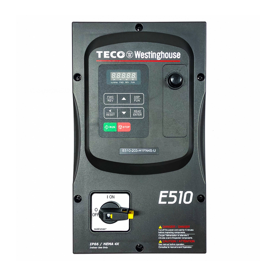
I P 6 6 / N E M A 4 X
0 . 4 - 2 . 2 k W / 0 . 5 - 3 H P
2 3 0 V C l a s s 3 ~
I P 6 6 / N E M A 4 X
0 . 4 - 1 5 k W / 0 . 7 5 - 2 0 H P
4 6 0 V C l a s s 3 ~
4 6 0 V
I P 6 6 / N E M A 4 X
0 . 4 5 - 1 8 . 5 k W / 1 - 2 5 H P
D O C U ME N T - T E C O - E 5 1 0 I M
V e r 0 1 : 2 0 1 5 . 0 8
Advertisement
Table of Contents
Troubleshooting

Related Manuals for TECO-Westinghouse E510


Summary of Contents for TECO-Westinghouse E510
- Page 1 I N V E R T E R E 5 1 0 S T A R T - U P A N D I N S T A L L A T I O N MA N U A L 2 3 0 V C l a s s 1 ~ I P 6 6 / N E M A 4 X 0 .
-
Page 2: Table Of Contents
**** STATEMENT **** Si Desea descargar el manual en español diríjase a este Link: www.tecowestinghouse.com Table of Contents Preface ................................0-1 1 Safety Precautions ............................. 1-1 1.1 Before Supplying Power to the Inverter ....................1-1 1.2 Wiring ................................ 1-2 1.3 Before Operation ............................1-3 1.4 Parameters Setting ........................... - Page 3 3.4 Inverter Exterior ............................3-5 3.5 Wire Gauges, Tightening Torque and Short Circuit Rating ..............3-8 3.6 Wiring Peripheral Power Devices ......................3-9 3.7 General Wiring Diagram .......................... 3-11 3.8 User Terminals ............................3-12 3.9 Power Terminals ............................. 3-15 3.10 Inverter Wiring ............................3-17 3.11 Input Power and Motor Cable Length ....................
- Page 4 7. Operation Method Configuration (Run / Stop) ..................7-1 7.1 Run / Stop from the Keypad ........................7-1 7.2 Run / Stop from External Switch / Contact or Pushbutton ................ 7-2 7.3 Run / Stop from Serial Communication RS485 ..................7-4 8.
- Page 5 00-15 Deceleration time 1 ..........................11-5 01-00 V/f curve selection ..........................11-6 03-00 ~ 03-05 Multi-function terminal function ....................11-9 03-11 ~ 03-12 Relay (R1A-R1C / R2A-R2C) output ................... 11-18 03-13 Frequency detection level ......................... 11-20 03-14 Frequency detection width ........................ 11-20 04-11 Analog Voltage &...
-
Page 6: Safety Precautions
1. Safety Precautions (English) 1.1 Before supplying Power to the Inverter Warning The main circuit must be correctly wired. For single phase supply use input terminals (R/L1, T/L3) and for three phase supply use input terminals (L1(L), L2, L3(N)). Terminals T1, T2, T3 must only be used to connect the motor. -
Page 7: Wiring
1.2 Wiring Warning Always turn OFF the power supply before attempting inverter installation and wiring of the user terminals. Wiring must be performed by a qualified personnel / certified electrician. Make sure the inverter is properly grounded. (230V Class: Grounding impedance shall be less than 100Ω. -
Page 8: Before Operation
1.3 Before Operation Warning Make sure the inverter capacity matches the parameters 13-00. Reduce the carrier frequency (parameter 11-01) If the cable from the inverter to the motor is greater than 80 ft (25m). A high-frequency current can be generated by stray capacitance between the cables and result in an overcurrent trip of the inverter, an increase in leakage current, or an inaccurate current readout. -
Page 9: Operation
1.5 Operation Warning Be sure to install all covers before turning on power. Do not remove any of the covers while power to the inverter is on, otherwise electric shock may occur. Do not connect or disconnect the motor during operation. This will cause the inverter to trip and may cause damage to the inverter. -
Page 10: Maintenance, Inspection And Replacement
1.6 Maintenance, Inspection and Replacement Warning Wait a minimum of five minutes after power has been turned OFF before starting an inspection. Also confirm that the charge light is OFF and that the DC bus voltage has dropped below 25Vdc. ... -
Page 11: Consignes De Sécurité (Français)
1. Consignes de sécurité (Français) 1.1 Avant d'alimenter le disque dur Avertissement Le circuit principal doit être correctement câblée. Pour les terminaux monophasés d'approvisionnement de l'utilisation des intrants (R/L1, T/L3) et de trois bornes d'entrée de l'utilisation de l'offre de phase (R/L1, S/L2, T/L3). -
Page 12: Avant L'opération
Attention La tension d'alimentation appliquée doit se conformer à la tension d'entrée spécifiée par le lecteur. (Voir la section signalétique du produit) Raccorder la résistance de freinage et de l'unité de freinage sur les bornes assignées. Ne pas brancher une résistance de freinage directement sur les bornes CC P (+) et N (-), sinon risque d'incendie. -
Page 13: Opération
1.5 Opération Avertissement Veillez à installer tous les couvercles avant de l'allumer. Ne retirez pas les capots pendant que l'alimentation du lecteur est allumé, un choc électrique peut se produire autrement. Ne pas brancher ou débrancher le moteur pendant le fonctionnement. Le variateur pourrai se déclencher et ainsi endommager le lecteur. -
Page 14: Mise Au Rebut Du Variateur
Attention Le variateur peut être utilisé dans un environnement avec une gamme de température allant de 14 ° -104 ° F (10-40 ° C) et l'humidité relative de 95% sans condensation. Le variateur doit être utilisé dans un environnement sans poussière, gaz, vapeur et humidité. 1.7 Mise au rebut du variateur Attention ... -
Page 15: Model Description
2. Model Description 2.1 Nameplate Data It is essential to verify the E510 inverter nameplate and make sure that the E510 inverter has the correct rating so it can be used in your application with the proper sized AC motor. -
Page 16: Inverter Models - Motor Power Rating
2.2 Inverter Models – Motor Power IP66 / NEMA 4X Type Supply Filter Switch Frame Model voltage (kW) Size (Vac) ◎ ◎ ◎ E510-2P5-H1FN4S 1 Phase ◎ ◎ ◎ E510-201-H1FN4S 0.75 200~240V +10%-15% ◎ ◎ ◎ E510-202-H1FN4S 50/60Hz ◎ ◎... -
Page 17: Environment And Installation
3. Environment and Installation 3.1 Environment The environment will directly affect the proper operation and the life span of the inverter. To ensure that the inverter will give maximum service life, please comply with the following environmental conditions: Protection Protection Class IP66 / NEMA 4X (Depending on models) Operating IP66 / NEMA 4X type: -10°C - +50°C (14-122 °F) -
Page 18: Warning Labels
3.2 Warning Labels Important: Warning information located on the front cover must be read upon installation of the inverter. -
Page 19: Removing The Front Cover And Keypad
3.3 Removing the Front Cover and Keypad Caution Before making any wiring connections to the inverter the front cover needs to be removed. IP66 / NEMA 4X Step 1: Unscrew cover and place cover next to the inverter... - Page 20 Step 2: Remove the rubber plugs and use the waterproof cable glands provided to connect cables. Step 3: Connect power & motor cables through the cable glands to the correct terminals Step 4: Connect power & motor cables through the cable glands to the correct terminals...
-
Page 21: Inverter Exterior
3.4 Inverter Exterior IP66/NEMA4X Single/Three phase: 230V 0.5~1HP Single phase: 230V 0.5~1HP Three phase: 230V 2HP; 460V 1~2HP E510-Frame 1 (IP66/NEMA 4X With/Without VR and disconnect switches depending on the model) - Page 22 Single/Three phase: 230V 2~3HP Single phase: 230V 2~3HP Three phase: 230V 5HP; 460V 3~5HP E510-Frame 2 (IP66/NEMA 4X With/Without VR and disconnect switches depending on the model)
- Page 23 Three phase: 230V 7.5~20HP; 460V 7.5~25HP E510-Frame 3 (IP66/NEMA 4X With/Without VR and disconnect switches depending on the model)
- Page 24 3.5 Wire Gauges, Tightening Torque, Terminal and Short Circuit Ratings. To comply with UL standards, use UL approved copper wires (rated 75° C) and round crimp terminals (UL Listed products) as shown in table below when connecting to the main circuit terminals. Model Cable Size Tightening torque...
-
Page 25: Wiring Peripheral Power Devices
3.6 Wiring Peripheral Power Devices Caution After power is shut off to the inverter the capacitors will slowly discharge. Do NOT touch and of the inverter circuitry or replace any components until the “CHARGE” indicator is off. Do NOT wire or connect/disconnect internal connectors of the inverter when the inverter is powered up or when powered off and the “CHARGE””... - Page 26 11 for peripheral devices. Input Noise filter: A filter must be installed when there are inductive loads affecting the E510 inverter. The inverter meets EN55011 Class A, category C3 when the Inverter TECO special filter is used.
-
Page 27: General Wiring Diagram
8:GND Reset Relay Output COM (NPN) (R1A) Factory Default Multi-Function Relay Output (R1C) +24V (PNP) E510 (R1B) Contact rating: E (Ground) 250 VAC < 1.0A 30 VDC < 1.0A Output Disable Relay Output +10V: Power for Analog Input Analog (max. 20mA) - Page 28 3.8 User Terminals (Control Circuit Terminals) R2A R2B 24V AI1 R1A R1B R1C AGND Jumper function descriptions Jumper Symbol Funct ion Si gn al R ef er en c e Note NPN Input J P 1 NPN/PNP selectable Factory default setting PNP Input 0~20mA / 4~20mA Set parameters...
-
Page 29: User Terminals
Description of User Terminals Type Terminal Terminal function Signal level Forward- Stop (Preset), Multi-function input terminal Reverse - Stop (Preset), Multi-function input terminal 24 VDC, 8 mA, Optical Digital Preset Speed0(5-02),Multi-function input terminal coupling isolation (Max, input voltage 30 VDC, Preset Speed1(5-03), Multi-function input terminal signal Input impedance 3.3kΩ) - Page 30 Notes: *1:Multi-function digital input can be referred to in this manual. - Group 03: External Terminals Digital Input / Output Function Group. *2:Multi-function analog input can be referred to in this manual.. - Group 04 - External Terminal Analog Signal Input (Output) Function Group. *3:Multi-function analog output can be referred to in this manual.
-
Page 31: Power Terminals
3.9 Power Terminals 230V: 0.5 ~ 20HP Terminal 460V: 1 ~ 25HP L1(L) Input Power Supply (For single phase use terminals L1(L) and L3(N) L3(N) Braking resistor connection terminal: For use in applications requiring a high inertia load to stop rapidly. (Refer to specifications of the braking resistor). - Page 32 Frame 2 230V: 2 ~ 3HP (Single Phase) 230V: 2 ~ 3HP (Single / Three Phase) 230V: 5HP (Three Phase) 460V: 3 ~ 5HP (Three Phase) Frame 3 & 4 230V: 7.5 ~ 20HP (Three Phase) 460V: 7.5 ~ 25HP (Three Phase) Notes: For wire gauges and screw torques, please refer to the table in section 3.6.
-
Page 33: Inverter Wiring
3.10 Inverter Wiring Wiring Precautions Do NOT remove any protective covers or attempt any wiring while input power is applied. Connect all wiring before applying input power. When making wiring changes after power up, remove input power and wait a minimum of five minutes after power has been turned off before starting. - Page 34 Always use a ground wire that complies with the local codes and standards for electrical equipment and minimize the length of ground wire. When using more than one inverter, be careful not to loop the ground wire, as shown below in Fig. 3.11.1. E510 E510 E510...
-
Page 35: Input Power And Motor Cable Length
3.11 Input Power and Motor Cable Length The length of the cables between the input power source and /or the motor and inverter can cause a significant phase to phase voltage reduction due to the voltage drop across the cables. The wire size shown in Tables 3.16.1 is based on a maximum voltage drop of 2%. -
Page 36: Power Input Wire Size And Nfb
3.14 Power Input Wire Size, and NFB The following table shows the recommended wire size for each frame of the E510. It depends on the application whether or not to install a circuit breaker. The NFB must be installed between the input power supply and the inverter input (L1 (L), L2, L3 (N)). -
Page 37: Inverter Specifications
3.16 Inverter Specification Product Specifications 230V class – Single Phase Model:E510-□□□- H1F(N4)(S) Horse power (HP) Suitable motor capacity (kW) 0.75 Rated output current (A) 10.5 Rated capacity (KVA) 2.90 4.00 Input voltage range(V) Single Phase:200~240V,50/60Hz Allowable voltage fluctuation +10%-15% Output voltage range(V) - Page 38 Product Specifications 230V class –Three Phase Model: E510-□□□- H3(N4) Horse power (HP) Suitable motor capacity (kW) Rated output current (A) 17.5 Rated capacity (KVA) 13.3 20.6 27.4 Input voltage range(V) Three phase :200~240V,50/60HZ Allowable voltage fluctuation +10%-15% Output voltage range(V)
- Page 39 Product Specifications 460V class –Three Phase Model: E510-□□□- H3(F)(PT) Horse power (HP) Suitable motor capacity ( kW ) 18.5 Rated output current (A) Rated capacity (KVA) 27.4 Three phase: 380~480V (+10%-15%),50/60Hz Input voltage range(V) Three phase: 0~480V Output voltage range(V)
-
Page 40: General Specifications
General Specifications Item E510 Control Mode V/F Control, Vector Control Output Frequency 0.01~650.00Hz Starting Torque 150%/1Hz(Vector) Speed Control Range 1:50 Digital input: 0.01Hz Setting resolution Analog input:0.06Hz/60Hz Keypad: Set directly with▲▼ keys or the VR on the Frequency keypad External Input Terminals:... - Page 41 Short-circuit output Electronic Circuit Protection terminal Grounding Fault Electronic Circuit Protection Protection for overheating of heat sink, The carrier Other protection frequency decreases based on the temperature, Fault features output, Reverse prohibit, Prohibit for direct start after power up and error recovery ,parameter lock up All frames include brake transistor Standard built-in RS485 communication (Modbus), One Communication control...
-
Page 42: Inverter Derating Based On Carrier Frequency
3.17 Inverter derating based on Carrier Frequency Frame 1 / 2 / 3 / 4 Single phase: 230V: 0.5~3HP; Single /Three phase: 230V: 0.5~3HP; Three phase: 230V: 2~20HP, 460V: 1~25HP) Current Rating 100% Carrier Frequency(kHz) Note: De-rate curve for ambient temperature of 104°F (40°C). De-rate curve for ambient temperature of 122°F (50°C). -
Page 43: Inverter Dimensions
3.18 Inverter Dimensions IP66 / NEMA 4X Dimensions Frame 1 (IP66 / NEMA 4X) Single phase: 230V 0.5~1HP Single / Three phase: 230V 0.5~1HP Three Phase: 230V 2HP; 460V 1~2HP 3-27... - Page 44 Unit: mm(inch) Model Dimensions (kg) E510-2P5-HN4R (7.87) E510-2P5-H1FN4S (7.87) (7.87) E510-201-HN4R (7.87) 150.8 133.3 248.7 230.2 214.2 49.5 10.6 E510-201-H1FN4S (5.94) (5.25) (9.79) (9.06) (8.43) (7.20) (1.95) (0.21) (0.21) (0.42) (7.87) (7.87) E510-401-H3N4 E510-401-H3FN4S (7.87) (7.87) E510-402-H3N4 E510-402-H3FN4S 3-28...
- Page 45 Frame 2 (IP66 / NEMA 4X) Single phase: 230V 2~3HP Single / Three phase: 230V 2~3HP Three Phase: 230V 5HP; 460V 3~5HP 3-29...
- Page 46 Unit: mm(inch) Model Dimensions (kg) 235.2 E510-202-HN4R (9.26) 235.2 235.2 E510-202-H1FN4S (9.26) (9.26) 235.2 E510-203-HN4R (9.26) 235.2 235.2 E510-203-H1FN4S 337.9 218.4 79.8 (9.26) (9.26) 5.98 (7.80) (4.53) (13.19) (12.40) (13.30) (8.60) (3.14) (0.28) (0.28) E510-205-H3N4 E510-403-H3N4 235.2 235.2 E510-403-H3FN4S (9.26) (9.26)
- Page 47 Frame 3 (IP66 / NEMA 4X) Three Phase: 230V 7.5~20HP; 460V 7.5~25HP 3-31...
- Page 48 Unit: mm(inch) Model Dimensions (kg) E510-208-H3N4 E510-210-H3N4 E510-215-H3N4 E510-220-H3N4 E510-408-H3N4 266.5 263.5 E510-408-H3FN4S (10.49) (10.37) 222.8 466.3 246.6 12.68 E510-410-H3N4 (8.77) (5.51) (18.11) (17.32) (18.36) (9.71) (3.78) (0.28) (0.28) 266.5 263.5 E510-410-H3FN4S (10.49) (10.37) E510-415-H3N4 266.5 263.5 E510-415-H3FN4S (10.49) (10.37)
-
Page 49: Keypad And Programming Functions
4. Keypad and Programming Functions 4.1 LED Keypad 4.1.1 Keypad Display and Keys LED Display Reverse Direction Forward Direction Status Indicator Status Indicator 8 button Membrane Keypad Frequency Potentiometer Run Key Stop Key DISPLAY Description 5 Digit LED Display Monitor inverter signals, view / edit parameters, fault / alarm display. LED INDICATORS Hz/RPM LED ON when frequency or line speed is displayed. - Page 50 4.1.2 Display Description Actual LED Display Actual LED Display Actual LED Display Actual LED Display ° Display output frequency Frequency Reference Set Frequency Reference LED lights on LED flashes Flashing digit At power-up the display will show the frequency reference setting, all LEDs are flashing. Press the ▲UP or ▼DOWN key to enter the frequency reference edit mode, use the ◄/ENT key to select which digit to edit (flashing).
- Page 51 LED display examples Seven Segment display Description 1. Displays the frequency reference at power-up 2. Display the actual output frequency in operation status. Display parameter code Display the setting value of parameter Display input voltage Display inverter current. Display DC Bus Voltage Display temperature Display PID feedback value.
- Page 52 4.1.3 LED Status description Hz/ RPM LED State Description Hz/RPM LED Display doesn’t show frequency or line speed Illuminated Display shows frequency or line speed Forward LED State Description FWD LED Inverter in reverse direction Illuminated Inverter is running in forward direction Flashing Forward direction active, no run command Reverse LED...
- Page 53 4.1.4 Power-Up Monitor Power Up: DSP/ DSP/ After 2 sec. Display at Power-up Frequency Reference Parameter Selection Change Monitor at Power-Up 12-00 Display selection Highest bit -> 0 0 0 0 0 <- Lowest bit The setting range for each bit is 0 ~ 8 from the highest bit to the lowest bit. Range 0: No display 4: Temperature...
- Page 54 Example: 12-00 = 12345 DSP/ Heatsink Temperature <4> DSP/ DSP/ DC Voltage <3> Output Voltage <2> DSP/ DSP/ PID Feedback <5> After 2 sec. Display Voltage Class Output Current <1> Parameter Selection at Power-up DSP/ DSP/ Frequency Reference 4.1.5 Modifying Parameters / Set Frequency Reference Frequency Short Press: DSP/FUN...
- Page 55 4.1.6 Operation Control Stopped Running Stopping Stopped Output Frequency Indicator Indicator...
-
Page 56: Parameters
4.2 Parameters Parameter group Name Group 00 Basic Parameters Group 01 V/F Control Parameters Group 02 Motor Parameters Group 03 External Digital Input and Output Parameters Group 04 External Analog Input and Output Parameters Group 05 Preset-Speed Parameters Group 06 Automatic Program Operation Parameters Group 07 Start /Stop Parameters... - Page 57 G r o u p 00: Basic parameters Factory Description Range Unit Note Setting 0:V/F Mode 00-00 Control Mode Selection 1:Vector Mode 00-01 Reserved 0:Keypad 1:External Run/Stop Control Main Run Command 00-02 2:Communication Source Selection 3:PLC 0:Keypad Alternative Run Command 00-03 1:External Run/Stop Control Source Selection...
- Page 58 G r o u p 01: V/F Control Parameters Factory Description Range Unit Note Setting 01-00 Volts/Hz Patterns 0~18 200V:170.0~264.0 01-01 V/F Max voltage 220.0/440.0 400V:323.0~528.0 01-02 Max Frequency 0.20 ~ 650.00 50.00/60.00 01-03 Max Frequency Voltage Ratio 0.0 ~ 100.0 100.0 01-04 Mid Frequency 2...
- Page 59 Group 03: External Digital Inputs and Relay Output Functions Factory Description Range Unit Note Setting 03-00 Multifunction Input Term. S1 0:Forward/Stop Command 03-01 1:Reverse/Stop Command Multifunction Input Term. S2 03-02 2:Speed Selection 1 Multifunction Input Term. S3 03-03 3:Speed Selection 2 Multifunction Input Term.
- Page 60 Group 03: External Digital Inputs and Relay Output Functions Factory Description Range Unit Note Setting ( Terminals R1A,R1B, R1C ) 1:Fault 2:Setting Frequency Reached 3:Frequency Reached. Set by (3-13±3-14) 4:Output Frequency Detection1(> 3-13) 5:Output Frequency Detection2(< 3-13) 6:Auto Restart 7:Momentary AC Power Loss 8:Rapid Stop 9:Base Block 10:Motor Overload Protection(OL1)
- Page 61 Group 04: External Analog Input and Output Parameters Factory Description Range Unit Note Setting (0): 0~10V (0~20mA) 0~10V (0~20mA) Analog Input Signal Type 04-00 (1): 0~10V (0~20mA) 2~10V (4~20mA) Select (AI1/AI2) (2): 2~10V (4~20mA) 0~10V (0~20mA) (3): 2~10V (4~20mA) 2~10V (4~20mA) 04-01 AI1 Signal Verification Scan Rate 1~200...
- Page 62 Group 05: Preset Speed Parameters Factory Description Range Unit Note Setting 0: Common Accel/Decel Accel/Decel 1 or 2 apply to all speeds Preset Speed Control 05-00 1: Individual Accel/Decel for each preset speed Mode Selection 0-15 apply to the selected preset speeds (Acc0/Dec0~Acc15/Dec15) Preset Speed 0 05-01...
- Page 63 Group 05: Preset Speed Parameters Factory Description Range Unit Note Setting 05-40 10.0 Preset Speed11-Dectime 05-41 10.0 Preset Speed12-Acctime 05-42 10.0 Preset Speed12-Dectime 05-43 10.0 Preset Speed13-Acctime 05-44 10.0 Preset Speed13-Dectime 05-45 10.0 Preset Speed14-Acctime 05-46 10.0 Preset Speed14-Dectime 05-47 10.0 Preset Speed15-Acctime 05-48...
- Page 64 Auto _ Run Mode 06-09 0.00 Frequency Command 9 Auto _ Run Mode 06-10 0.00 Frequency Command10 Auto _ Run Mode 06-11 0.00 Frequency Command 11 Auto _ Run Mode 06-12 0.00 Frequency Command 12 Auto _ Run Mode 06-13 0.00 Frequency Command 13 Auto _ Run Mode...
- Page 65 Auto_ Run Mode Running 06-32 Direction 0 Auto_ Run Mode Running 06-33 Direction 1 Auto_ Run Mode Running 06-34 Direction 2 Auto_ Run Mode Running 06-35 Direction 3 Auto_ Run Mode Running 06-36 Direction 4 Auto_ Run Mode Running 06-37 Direction 5 Auto_ Run Mode Running 06-38...
- Page 66 Group 07: Start/Stop Parameters Factory Description Range Unit Note Setting 0: Momentary Power Loss and Restart Disable Momentary Power Loss and 07-00 Restart 1: Momentary Power Loss and Restart Enable 07-01 Auto Restart Delay Time 0.0~800.0 Number of Auto Restart 07-02 0~10 Attempts...
- Page 67 Group 08: Protection Parameters Factory Description Range Unit Note Setting xxxx0: Enable Trip Prevention During Acceleration xxxx1: Disable Trip Prevention During Acceleration xxx0x: Enable Trip Prevention During Deceleration xxx1x: Disable Trip Prevention During Deceleration 08-00 Trip Prevention Selection 01000 xx0xx: Enable Trip Prevention in Run Mode xx1xx: Disable Trip Prevention in Run Mode...
- Page 68 Group 08: Protection Parameters Factory Description Range Unit Note Setting 0: Stop Output After Over Torque Detection (Free Run to Over torque protection Stop) 08-14 action 1: Continue Running After Over Torque Detection (Display only OL3) Over Torque Detection 08-15 30~300 Level Over Torque Detection...
- Page 69 Group 10: PID Parameters Factory Description Range Unit Note Setting 0: Potentiometer on Keypad 1: Analog Signal Input. (AI1) PID Target Value Selection 2: Analog Signal Input. (AI2) 10-00 (When 00-05\00-06=6 This Function is 3: Frequency Set by Communication Enabled) 4: Keypad Frequency Parameter 10-02 0: Potentiometer on Keypad...
- Page 70 Group 10: PID Parameters Factory Description Range Unit Note Setting 10-22 Min PID Feedback Setting Level 0 ~999 Group 11: Auxilary Parameters Factory Description Range unit Note Setting 0: Reverse Command is Enabled 11-00 Reverse Operation Control 1: Reverse Command is Disabled 11-01 Carrier Frequency (kHz) 1~16...
- Page 71 Group 12: Monitoring Parameters Factory Description Range Unit Note Setting 00000~88888 Each digit can be set from 0 to 8 as listed below. 0: Default Display (Frequency and Parameters) 1:Output Current 2:Output Voltage 12-00 3:DC Voltage Extended Display Mode 00000 4:Temperature 5:PID Feedback 6:Analog Signal Input.
- Page 72 Group 12: Monitoring Parameters Factory Description Range Unit Note Setting Display of Inrush Current 12-08 0~100 Suppression Circuit Display of Control Circuit 12-09 0~100 Capacitors 12-10 Reserved Output Current when 12-11 ---- Fault Appeared Output Voltage when 12-12 ---- Fault Appeared Output Frequency when 12-13 ----...
- Page 73 Group 14: PLC Parameters Factory Description Range unit Note Setting 14-00 Setting Value1 of T1 0~9999 14-01 Setting Value1 of T1 (mode 7) 0~9999 14-02 Setting Value1 of T2 0~9999 14-03 Setting Value1 of T2 (mode 7) 0~9999 14-04 Setting Value1 of T3 0~9999 14-05 Setting Value1 of T3 (mode 7)
- Page 74 14-45 Setting Value1 of MD4 0~65535 14-46 Setting Value2 of MD4 0~65535 14-47 Setting Value3 of MD4 1~65535 Group 15: PLC Monitoring Parameters Factory Description Range unit Note Setting 15-00 Current Value of T1 0~9999 15-01 Current Value of T1(mode 7) 0~9999 15-02 Current Value of T2...
-
Page 75: Check Motor Rotation And Direction
5. Check motor rotation and direction This test is to be performed solely from the inverter keypad. Apply power to the inverter after all the electrical connections have been made and protective covers have been re-attached. At this point, DO NOT RUN THE MOTOR, the keypad should display as shown below in Fig. -
Page 76: Speed Reference Command Configuration
6. Speed Reference Command Configuration The inverter offers users several choices to set the speed reference source. The most commonly used methods are described in the next sections. Frequency reference command is selected with parameter 00-05. 00-05: Main Frequency Command (Frequency Source) This function sets the frequency command source. - Page 77 6.2 Reference from External Analog Signal (0-10V / 4-20mA) Analog Reference: 0 – 10 V (Setting 00-05 = 2) AGND Common/0V, GND Analog Control Terminals / Input AI1 User Terminals 0 – 10 V Analog Reference: Potentiometer / Speed Pot (Setting 00-05 = 2) AGND Analog Common/0V, GND...
- Page 78 Analog Reference: 4 – 20mA (Setting 00-05 = 2) AGND Common, GND Control Terminals / Analog Input AI2 User Terminals Set jumper JP3 to position1 & 2 4 – 20mA...
-
Page 79: Reference From Serial Communication Rs485
6.3 Reference from Serial Communication RS485 (00-05=5) CON2 8 7 6 5 4 3 2 1 Control board Cable Shield RS485 Port RS485 PLC / Computer Connection To set the speed reference for the inverter via serial communication parameter 00-05 has be set to “5” for frequency command via serial communication. - Page 80 Examples: Frequency Reference Command: 10.00 Hz (Inverter Node Address: 01) Command String (hexadecimal): 01 06 25 02 03 E8 23 B8 To set the frequency reference to 10.00, a value of ‘1000’ (03E8h) has to be send to the inverter. Frequency Reference Command: 30.00 Hz (Inverter Node Address: 01) Command String (hexadecimal): 01 06 25 02 0B B8 24 44 To set the frequency reference to 30.00, a value of ‘3000’...
-
Page 81: Reference From Pulse Input
6.4 Reference from Pulse Input (00-05=7) Serial pulse input Specification Low Input Level: 0.0 to 10 Vdc High Input Level: 13 to 30 Vdc Duty cycle: (ON / OFF) 30 % to 70% AGND Pulse Input frequency range: 10 to 200Hz Set Pulse Input Setup as Frequency Reference Set parameter 00-05 to 7 and 03-02 to 26 to use the pulse input terminal S3 as the frequency reference source. -
Page 82: Change Frequency Unit From Hz To Rpm
6.5 Change Frequency Unit from Hz to rpm 12-03 Custom Units (Line Speed) Display Mode 【0~65535】Rpm Range Set motor rated RPM for the inverter to display the actual motor speed based on the output frequency. Motor synchronous speed = 120 x Rated frequency ÷ Number of poles. 12- 04 Custom Units (Line Speed) Display Mode 【0】:Drive Output Frequency is Displayed... -
Page 83: Operation Method Configuration (Run / Stop)
7. Operation Method Configuration (Run / Stop) The inverter offers users several choices to run and stop from different sources. The most commonly used methods are described in the next sections. Operation command is selected with parameter 00-02. 00-02: Run Command Selection This function sets the frequency command source. -
Page 84: Run / Stop From External Switch / Contact Or Pushbutton
7.2 Run/Stop from External Switch / Contact or Pushbutton (00-02=1) Use an external contact or switch to Run and Stop the inverter. Set parameter 00-04 to 0 for 2-wire operation, multi-function input terminal S1 is set to run operation forward command. - Page 85 Momentary Contacts (Push Buttons) Use push button / momentary switch to Run and Stop the inverter. Set parameter 00-04 to 2 for 3-wire operation, multi-function input terminal S1 is set to run operation, S2 for stop operation and S3 for forward/reverse command. 00-02 Run Command Selection = 1 AGND Reverse direction...
-
Page 86: Run / Stop From Serial Communication Rs485
7.3 Run/Stop from Serial Communication RS485 (00-02=2) CON2 8 7 6 5 4 3 2 1 Control board Cable Shield RS485 Port RS485 PLC / Computer Connection To control (Run/Stop) the inverter via serial communication parameter 00-02 has be set to a “2” for communication control. - Page 87 Examples: Run Forward Command (Inverter Address: 01) Command String (hexadecimal): 01 06 25 01 00 01 12 C6 Run Reverse Command (Inverter Address: 01) Command String (hexadecimal): 01 06 25 01 00 03 93 07 Stop Command (Inverter Address: 01) Command String (hexadecimal): 01 06 25 01 00 00 D3 06 Note: The last 2 bytes of the command strings consist of a CRC16 checksum, please refer to section 4.5 of the instruction manual for additional information.
-
Page 88: Motor And Application Specific Settings
8. Motor and Application Specific Settings It is essential that before running the motor, the motor nameplate data matches the motor data in the inverter. 8.1 Set Motor Nameplate Data (02-01, 02-05) 02-05 Motor Rated Power The nominal motor rated capacity is set at the factory. Please verify that the motor name plate data matches the motor rated capacity shown in parameter 02-05. -
Page 89: Acceleration And Deceleration Time
8.2 Acceleration and Deceleration Time (00-14, 00-15) Acceleration and Deceleration times directly control the system dynamic response. In general, the longer the acceleration and deceleration time, the slower the system response, and the shorter time, the faster the response. An excessive amount of time can result in sluggish system performance while too short of a time may result in system instability. - Page 90 8.3 Torque Boost (V/f Curve Modification) (01-10) This parameter sets the relationship between output frequency and output voltage. Constant torque applications have the same torque requirements at low speed as well as at high speed. Initial Setup For Variable Torque / Normal Duty applications set parameter 01-10 to an initial value of 0.5. For Constant Torque / Heavy Duty applications set parameter 01-10 to an initial value of 1.0.
-
Page 91: Rapid Stop
8.4 Rapid Stop Deceleration time 2 is used in combination with multi-function digital input function #14 (Rapid stop). When rapid stop input is activated the inverter will decelerate to a stop using the Deceleration time 2 (00-17) and display the [E.S.] condition on the keypad. -
Page 92: Forward And Reverse Jog
8.5 Forward and Reverse Jog The jog forward command is used in combination with multi-function digital input function #6 (Jog Forward) and the jog reverse command is used in combination with multi-function digital input function #7 (Jog Reverse). Example: Jog Forward input terminal S5 (03-04 = 06) and Jog Reverse input terminal S6 (03-05=7) AGND Common Control Terminals /... -
Page 93: Analog Output Setup
8.6 Analog Output Setup Signal: Use parameter 04-11 to select the analog output signal for AO and parameter 04-16 to select the analog output signal for AO2. Gain: Use parameter 04-12 to adjust the gain for AO. Adjust the gain so that the analog output (10V) matches 100% of the selected analog output signal (04-11). -
Page 94: Using Pid Control For Constant Flow / Pressure Applications
9. Using PID Control for Constant Flow / Pressure Applications 9.1 What is PID Control? The PID function in the inverter can be used to maintain a constant process variable such as pressure, flow, temperature by regulating the output frequency (motor speed). A feedback device (transducer) signal is used to compare the actual process variable to a specified setpoint. - Page 95 Example 1: Example 2: Gain = 1.0 Gain = 2.0 Set-Point = 80% Set-Point = 80% Feedback = 78% Feedback = 78% Error = Set-point - Feedback = 2% Error = Set-point - Feedback = 2% Control Error = Gain x Error = 2% Control Error = Gain x Error = 4% Please note that an excessive gain can make the system unstable and oscillation may occur.
-
Page 96: Connect Transducer Feedback Signal
Commonly used PID control modes 1: Forward operation: PID operation enabled, motor speeds increases when feedback signal is smaller than set-point (most fan and pump applications) 3: Reverse operation: PID operation enabled, motor slows down when feedback signal is smaller than set-point (e.g. -
Page 97: Engineering Units
Feedback Signal 0 – 10V (10-01 = 1) AGND Common/0V, GND Analog Control Terminals / Input AI1 User Terminals 0 – 10 V 9.3 Engineering Units PID Feedback Display Scaling The PID feedback signal can be scaled to represent actual engineering units. Use parameter 10-21 to set the feedback signal gain for the feedback signal range maximum and parameter 10-22 to the feedback signal minimum. -
Page 98: Sleep / Wakeup Function
9.4 Sleep / Wakeup Function The PID Sleep function can be used to prevent a system from running at low speeds and is frequently used in pumping application. The PID Sleep function is turned on setting parameter 10-17 to a value greater than 0. The inverter output turns off when the PID output falls below the PID sleep level (10-17) for the time specified in the PID sleep delay time parameter (10-18). -
Page 99: Troubleshooting, Fault Diagnostics And Maintenance
10. Troubleshooting, Fault Diagnostics and Maintenance 10.1 General Inverter fault detection and early warning / self-diagnosis function. When the inverter detects a fault, a fault message is displayed on the keypad. When the inverter detects a warning / self-diagnostics error, the digital operator will display a warning or self-diagnostic code, the fault output does not energize in this case. - Page 100 LED display Description Cause Possible solutions Inverter faults that cannot be reset DC bus voltage is Under voltage lower than the UV detection level or the pre-charge The input voltage is too low. Check the input voltage. contactor is not ...
- Page 101 Inverter faults that can be reset manually or via automatic restart LED display Description Cause Possible solutions OC-A The inverter output over current at Extend acceleration / Acceleration / Deceleration time is too short. current exceeds the acceleration ...
- Page 102 LED display Description Cause Possible solutions Ud-C Under Current Output under Output current < Output under current Set level according to current detection detection level. application. Internal motor Check V/f curve. Motor overload Voltage setting V/F mode too high, resulting in overload protection ...
- Page 103 Keypad Operation Error Codes LED display Description Cause Possible solutions 1.Parameter Locked already locked Attempt to modify frequency parameter while 2.Motor direction 13-06>0. Adjust 13-06 Attempt to reverse direction when 11-00=1 locked Adjust 11-00 Parameter (13 - 07) enabled, set the correct 3.Parameter password will show LOC.
- Page 104 Special Condition Error Codes LED display Fault Description StP0 Zero speed at stop Occurs when preset frequency <0.1Hz If the inverter is set for external terminal control mode (00-02/00-03=1) and StP1 Fail to start directly direct start is disabled (07-04=1) ...
-
Page 105: General Troubleshooting
10.3 General Troubleshooting Status Check Possible Solution Wiring must match U, V, and W terminals of the Motor runs in Check inverter output wiring. motor. wrong direction Check control terminal wiring. Check for correct wiring. Check control terminal wiring. Check for correct wiring. Unable to Check the Frequency regulate... -
Page 106: Routine And Periodic Inspection
10.4 Routine and Periodic Inspection To ensure stable and safe inverter operation it is recommended to perform inverter maintenance at regular intervals. Use the checklist below as a guideline for inspection. Disconnect power and wait approximately 5 minutes to make sure no voltage is present on the output terminals before carrying out any inspection or maintenance. - Page 107 Circuit boards and components Check for damage to ◎ PCBs Clean or Printed circuit replace the Check for discolored, board ◎ circuit board overheated, or burned Correct parts Visual check Check for unusual odor component ◎ Replace or leakage condition Capacitor capacitor or Check for any physical...
-
Page 108: Routine Maintenance
10.5 Routine Maintenance To ensure stable and safe inverter operation it is recommended to perform routine inverter maintenance at regular intervals. Use the checklist below as a guideline for inspection. 1. Maintenance Check List Ensure that temperature and humidity where the inverter is installed falls within the specification, make sure correct ventilation is provided. -
Page 109: Commonly Used Parameters
11. Commonly used parameters 00-02 Main Run Command Source Selection 00-03 Alternative Run Command Source Selection 【0】:Keypad control 【1】:External terminal control Range 【2】:Communication control 【3】:PLC Note: To switch the command source between the setting of main (00-02) and alternative (00-03) assign one of the DI (S1 to S6) to be the “Run Command Switch Over”... - Page 110 ■ 3-wire operation Set parameter 00-04 to 3 for 3-wire program initialization, multi-function input terminal S1 is set to run operation, S2 for stop operation and S3 for forward/reverse command. Note: Terminal S1 must be closed for a minimum of 50ms to activate operation. Operation (normally open Momentary switch)
-
Page 111: Main Frequency Command Source Selection
Main Frequency Command Source Selection 00-05 Alternative Frequency Source Selection 00-06 【0】:Up/Down on Keypad 【1】:Potentiometer on Keypad 【2】:External AI1 Analog Signal Input 【3】:External AI2 Analog Signal Input Range 【4】:External Up/Down Frequency Control 【5】:Communication Setting Frequency 【6】:PID Output Frequency 【7】:Pulse Input 00-05/00-06= 0: Keypad Use the keypad to enter the frequency reference or by setting parameter 05-01 (frequency reference 1). - Page 112 Main Frequency Reference Command 2KΩ (voltage or current input) Main Frequency Reference Command (voltage or current input) AGND Figure 11.4 Analog input as main frequency reference command 00-05/00-06= 4: Terminal UP / DOWN The inverter accelerates with the UP command closed and decelerates with the DOWN command closed. Please refer to parameter 03-00 ~ 03-05 for additional information.
-
Page 113: Acceleration Time 1
00-14 Acceleration Time 1 【0.1~3600.0】Sec Range 00-15 Deceleration Time 1 【0.1~3600.0】Sec Range Notes: - Acceleration time is the time required to accelerate from 0 to 100% of maximum output frequency. - Deceleration time is the time required to decelerate from 100 to 0% of maximum output frequency. - Maximum frequency is set by parameter 01-02. -
Page 114: V/F Curve Selection
01-00 Volts/Hz Patterns (V/F) 【0~18】 Range The V/F curve selection is enabled for V/F mode. Make sure to set the inverter input voltage parameter 01-14. There are three ways to set V/F curve: (1) 01-00 = 0 to 17: choose any of the 18 predefined curves (0 to 17). (2) 01-00 = 18, use 01-02~01-09 and 01-12 ~ 01-13. - Page 115 TYPE 50Hz 60Hz 01-00 V/F pattern 01-00 V/F pattern (V)% (V)% =【0】 =【9】 1.5 2.5 (V)% (V)% =【1】 =【10】 =【2】 =【11】 1.5 3.0 1.32.5 =【3】 =【12】 (V)% (V)% =【4】 =【13】 =【5】 =【14】 (V)% (V)% =【6】 =【15】 =【7】 =【16】 =【8】 =【17】 (V) 100% is the maximum output voltage.
- Page 116 01-00 B (Xb) C (Xc) 0 / 9 7.5% 4.5% 1 / 10 10.0% 7.0% 11.0% 8.5% 12.0% 9.5% 17.5% 4.0% 25.0% 5.0% 11.0% 8.0% 12.0% 9.0% 20.5% 7.0% 28.5% 8.0% 6 / 15 45.0% 1.0% 7 / 16 55.0% 1.0% 8 / 17 65.0%...
- Page 117 03-00 Multifunction Input Term. S1 03-01 Multifunction Input Term. S2 03-02 Multifunction Input Term. S3 03-03 Multifunction Input Term. S4 03-04 Multifunction Input Term. S5 03-05 Multifunction Input Term. S6 【0】:Forward/Stop Command---------------- (Parameters 00-02/00-03=1& 00-04) 【1】:Reverse/Stop Command---------------- (Parameters 00-02/00-03=1& 00-04) 【2】:Speed Selection 1 【3】:Speed Selection 2 【4】:Speed Selection 3...
- Page 118 Set 00-04=【0】; S1:03-00=【0】 (FWD/STOP); S2:03-01=【1】 (REV/STOP); (FWD/STOP) (REV/STOP) E510 Note: If both forward and reverse commands are active the inverter treats this as a STOP command. 3-Wire control method Example: Two separate push buttons for RUN & STOP and two position selector switch for FWD/REV Set 00-04 =【2】, (3 wire control mode), to set terminals S1, S2 and S3 for 3-Wire control...
- Page 119 03-00~03-05 =【5, 4, 3, 2】Preset speed selections Digital input S1 to S6 can be used to select between 16 different preset speeds (Preset speed 0 to 15). Four speed selection bits are available and can be assigned to any of the digital input. The selected preset speed is based on the combination of the speed selection bits shown in the table below.
- Page 120 03-0X =【06】: Forward jog run command, uses jog frequency parameter 00-18. Note: Jog command has a higher priority than other frequency reference commands. Jog command uses stop mode set in parameter 07-09 when Jog command is active > 500ms. 03-0X =【07】: Reverse jog run command, uses jog frequency parameter 00-18.
- Page 121 Example: 00-12 (Frequency upper limit) =60Hz 03-00= 0 (Terminal S1 FWD/STOP) 00-14 (accelerating time 1) = 10 sec 00-16 (accelerating time 2) =5 sec S1 On S1 Off 60Hz (accel time 2) (accel time 1) 03-00~03-05=【11】Disable Acc/Dec function When activated suspends the acceleration / deceleration operation and maintains the output frequency at current level.
- Page 122 03-00~03-05=【13】Main/ Alternative Frequency Source Select When active the Alternative Frequency Source parameter 00-06 is used, otherwise Main Frequency Source is used parameter 00-05. 03-00~03-05=【14】Rapid Stop (controlled deceleration stop) When active inverter decelerates to stop using deceleration time 2. 03-00~03-05=【15】Base Block (Coast to stop) When active the inverter output is turned off.
- Page 123 03-00~03-05=【23】Counter Reset When active resets counter to 0. 03-00~03-05=【24】PLC Input Input used for PLC logic. 03-02=【25】Pulse Input-Width Measure (Available for S3 Input only) When 03-02=25, S3 is used for pulse width measurement. Related parameters: 00-05=7 (Pulsed Speed Control) 03-27= 0.01~0.20 kHz (Pulse Input Frequency) 03-28=0.01~9.99 Inverter Frequency = duty cycle x (00-12) x (03-28) Hz (Limited by the Frequency Upper limit) To adjust speed through pulse input duty cycle, set parameters as follows:...
- Page 124 Related Parameters: 00-05=7 (Pulsed Speed Control) 03-02=26 (S3 is the pulse input- frequency measurement) 03-28=0.01~9.99 Inverter Frequency = f x (3-28) Hz, f: Pulse Input Frequency (Limited by the Frequency Upper limit) Set the following parameters to use pulse input for speed command: 00-05=7 03-02=26 03-28=1 (adjust if required)
- Page 125 03-00~03-05=【28】Fire Mode Function When active inverter runs at maximum speed (parameter 00-12) ignoring any protective functions. Fire Mode function can be used for applications following a fire where it is necessary for a motor to continue running without interruption. Example: Smoke exhaust fans used in buildings for fire evacuation. Caution ...
- Page 126 03-11 Multifunction Output Relay RY 1 functions. ( Terminals R1C,R1B, R1A ) 03-12 Multifunction Output Relay RY 2 functions. ( Terminals R2B, R2A ) 【0】:Run 【1】:Fault 【2】:Set Frequency within the preset range. -------------------------------( refer to 03-14) 【3】:Set Frequency reached. As set by (3-13±3-14) -------------- ( refer to 03-13/03-14) 【4】:Output Frequency Detection 1 (>...
-
Page 127: Relay (R1A-R1C / R2A-R2C) Output
When Output Freq. = Preset Freq. Reached Setting (03-13) – Preset Freq. Reached Detection Range (03-14), Relay Output will be ON Preset Freq. Reached Setting (03-13) Preset Freq. Reached Detection Range (03-14) (03-13) – (03-14) Output Freq. Time (03-13) - (03-14) Preset Freq. - Page 128 When Output Frequency > Preset Frequency Reached Setting (03-13), Relay output is ON Setting Freq. (03-13) Output Freq. Time Output Freq. (03-13) Setting Freq. Run Command Relay Output 03-11=【5】: Output Frequency Detection 2 Output is active when the output frequency is below the frequency detection level (03-13) and turns off when the output frequency falls below frequency detection level (03-13).
-
Page 129: Analog Voltage & Current Input Selections Ai1/Ai2
03-11/03-12=【20】: Zero Speed Output Frequency => Minimum Frequency (01-08, Fmin) Output Frequency < Minimum Frequency (01-08, Fmin) Output Frequency 01-08(Fmin) Zero Speed 04-00 Analog Voltage & Current Input Selections AI1/AI2 Range 【0】: 0~10V (0~20mA) 0~10V (0~20mA) 【1】: 0~10V (0~20mA) 2~10V (4~20mA) 【2】: 2~10V (4~20mA) 0~10V (0~20mA) 【3】: 2~10V (4~20mA) - Page 130 04-01 AI1 Signal Verification Scan Rate 【1~200】2msec Range 04-02 AI1 Gain 【0 ~ 1000】% Range 04-03 AI1 Bias 【0~ 100】% Range 04-04 AI1 Bias Selection 【0】: Positive 【1】: Negative Range 04-05 AI1 Slope 【0】: Positive 【1】: Negative Range 04-06 AI2 signal verification Scan Rate 【1~200】2msec Range 04-07...
- Page 131 04-03 04-03 Bias Upper Bias 100% 60Hz Frequency 100% 60Hz 30Hz 30Hz (2) Negative Bias type (04-04= 1), Bias (04-03) and Slope (04-05). Figure3: Figure4: 04-02 04-03 04-04 04-05 04-02 04-03 04-04 04-05 100% 100% Upper Upper 60Hz 60Hz Frequency Frequency 30Hz 30Hz...
- Page 132 (4) Various other examples of analog input scaling and modification are shown in following figures 7,8,9 & 10. Figure7: Figure8: 04-02 04-03 04-04 04-05 04-02 04-03 04-04 04-05 200% 200% 04-03 04-03 bias Upper bias 100% 60Hz Upper Frequency 100% 60Hz Frequency 37.5Hz...
-
Page 133: Analog Output A01 Function Selection
04-11 Analog Output (AO) Function Selection. 【0】:Output Frequency Range 【1】:Frequency Command 【2】:Output Voltage 【3】:DC Bus Voltage 【4】:Output Current Example: Set 04-11 as required according to the table below. 04-11 Xmax 【0】 Output frequency upper frequency limit 【1】 Frequency Setting upper frequency limit 【2】... -
Page 134: Auto Restart Delay Time
07-00=0: Inverter trips on “UV” fault on power loss and will not restart. 07-00=1: Inverter resumes operation at half of the output frequency before power-loss after power has been restored. There is no limitation on the number of restarts. The momentary power loss function is enabled as long as the inverter CPU still has power and the inverter will restart when power is restored based on the setting of parameters 00-02, 07-04 and status of External run command. -
Page 135: Trip Prevention Selection
The automatic restart function can be used for the following faults. Please note that when the fault is not listed in the table the inverter will not attempt an automatic restart. OC-S Over current at start OV-C Over voltage during operation / deceleration Input phase loss Over current Motor overload... -
Page 136: Display Mode
below the setting of parameter 08-0301 after which acceleration resumes back to the target frequency. 08-04 Over Voltage Prevention Level During Run Mode 【350.0VDC~390.0VDC】(230V class) 【700.0VDC~780.0VDC】(460V class) Range Over voltage prevention level can be set by parameter 08-04 if needed. ... - Page 137 12-04 Custom Units (Line Speed) Display Mode 【0】:Drive Output Frequency is Displayed 【1】:Line Speed is Displayed in Integer (xxxxx) Range 【2】:Line Speed is Displayed with One Decimal Place (xxxx.x) 【3】:Line Speed is Displayed with Two Decimal Places (xxx.xx) 【4】:Line Speed is Displayed with Three Decimal Places (xx.xxx) 12-04≠0, line speed is displayed while the inverter is running or stopped.
-
Page 138: Reset Drive To Factory Settings
13-02 Fault Log Display(Latest 3 faults) Range ---- Last three faults are stored using FIFO mechanism, whenever a new fault occurs the previous faults are pushed down. Example: Fault stored in 2.xxx is moved to 3.xxx and 1.xxx is moved to 2.xxx. The most recent fault will be stored on position 1.xxx. - Page 139 Appendix: UL Instructions Danger Electric Shock Hazard Do not connect or disconnect wiring while the power is on. Failure to comply will result in death or serious injury. Warning Electric Shock Hazard Do not operate equipment with covers removed. Failure to comply could result in death or serious injury. The diagrams in this section may show inverters without covers or safety shields to show details.
- Page 140 Warning Fire Hazard Tighten all terminal screws to the specified tightening torque. Loose electrical connections could result in death or serious injury by fire due to overheating of electrical connections. Do not use an improper voltage source. Failure to comply could result in death or serious injury by fire. Verify that the rated voltage of the inverter matches the voltage of the incoming power supply before applying power.
- Page 141 UL Standards The UL/cUL mark applies to products in the United States and Canada and it means that UL has performed product testing and evaluation and determined that their stringent standards for product safety have been met. For a product to receive UL certification, all components inside that product must also receive UL certification. ...
- Page 142 Wire Gauge Crimp Drive Model Terminal Tool Insulation Cap Terminal mm2 , (AWG) R/L1 / S/L2 / U/T1 / V/T2 / E510 Screws Model No. Machine No. Model No. T/L3 W/T3 2.1 (14) M3.5 R2-3.5 Nichifu NH 1 / 9 TIC 2 3.3(12)
- Page 143 Recommended Input Fuse Selection Fuse Type Drive Model E510 Manufacturer: Bussmann / FERRAZ SHAWMUT Model Fuse Ampere Rating (A) 230 V Class Single / Three-Phase Drives 2P5-HXXX Bussmann 20CT 690V 20A 201-HXXX Bussmann 20CT 690V 20A 202-HXXX Bussmann 35FE 690V 35A...
- Page 144 This inverter has undergone the UL short-circuit test, which certifies that during a short circuit in the power supply the current flow will not rise above value. Please see electrical ratings for maximum voltage and table below for current. • The MCCB and breaker protection and fuse ratings (refer to the preceding table) shall be equal to or greater than the short-circuit tolerance of the power supply being used.
- Page 145 ■ 08-05 Motor Overload Protection Selection The inverter has an electronic overload protection function (OL1) based on time, output current, and output frequency, which protects the motor from overheating. The electronic thermal overload function is UL-recognized, so it does not require an external thermal overload relay for single motor operation. This parameter selects the motor overload curve used according to the type of motor applied.
- Page 146 ■ 08-12 Motor Overload Protection Curve 08-12 Start-up mode of overload protection operation (OL1) 0: Motor Overload Protection for General loads (OL=103 %) (150% for 1 Minute) Range 1: Motor Over load Protection for HVAC (Fan & Pump) (OL=113%) (123% for 1 Minute) 08-12=0: For constant torque applications with a load less than 103% of the motor rated current.
Need help?
Do you have a question about the E510 and is the answer not in the manual?
Questions and answers