Advertisement
Table of Contents
- 1 Standard Compliance
- 2 Engineering Data
- 3 Derating Curve
- 4 End Plate
- 5 Mounting Brackets
- 6 Safety Precautions
- 7 Warning Indications
- 8 Powerboost Function
- 9 Overcurrent Protection
- 10 Charging a Battery
- 11 Series Operation
- 12 Parallel Operation
- 13 Backup Operation
- 14 Terms and Conditions Agreement
- Download this manual
New Product
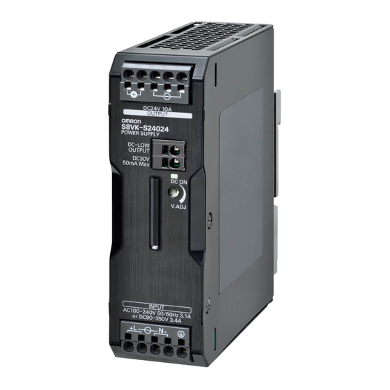
Switch Mode Power Supply
S8VK-S
A Perfect Fit for Small Control Panels
Coated PCBs for Better Resistance
to Environment
Easy Wiring by Push-in Plus
Technology
• Operation possible at ambient temperatures from
-40 to 70°C.
• Side-by-side mounting possible (up to 55°C). *1
• DC input supported (90 to 350 VDC).
• Power Boost function at 120% (30/60 and 120 W);
Power Boost function at 150% (240 and 480 W).
• Low-voltage detection output (only for 240 and
480 W).
• Vibration resistance to 5G, and 300-VAC abnormal
input voltage supported for 1 second.
• ANSl/ISA 12.12.01.
• Certification for 3,000 m altitude (UL/EN/IEC
60950-1 and EN 50178).
• Complies with EN/IEC 61558-2-16.
• Lloyd's, DNV GL (Except 30 W)
• Conforms to SEMI F47-0706.
• RoHS compliant
*1. For front, side-by-side mounting, see page 18.
Model Number Structure
Model Number Legend
Note: Not all combinations are possible. Refer to List of Models in Ordering Information, below.
S8VK- S@@@@@
1
2
1. Power Ratings
030: 30 W
060: 60 W
120: 120 W
240: 240 W
480: 480 W
Ordering Information
Note: For details on normal stock models, contact your nearest OMRON representative.
Power ratings
Rated input voltage
30 W
100 to 240 VAC
60 W
(allowable range:
120 W
85 to 264 VAC or
240 W
90 to 350 VDC)
480 W
(30/60/120/240/480-W Models)
2. Output voltage
24: 24 V
Rated output voltage
24 V
24 V
24 V
24 V
24 V
Refer to Safety Precautions for All Power Supplies and Safety
!
Precautions on page 17.
Rated output current
Maximum boost current
1.3 A
1.56 A
2.5 A
3 A
5 A
6 A
10 A
15 A
20 A
30 A
LR
Model number
S8VK-S03024
S8VK-S06024
S8VK-S12024
S8VK-S24024
S8VK-S48024
1
Advertisement
Table of Contents

Related Manuals for Omron S8VK-S06024


Summary of Contents for Omron S8VK-S06024
- Page 1 060: 60 W 120: 120 W 240: 240 W 480: 480 W Ordering Information Note: For details on normal stock models, contact your nearest OMRON representative. Power ratings Rated input voltage Rated output voltage Rated output current Maximum boost current...
- Page 2 S8VK-S Specifications Ratings, Characteristics, and Functions Power rating 30 W 60 W 120 W Item Output voltage 24 V 24 V 24 V 115 VAC input *1 87% typ. 87% typ. 90% typ. Efficiency 230 VAC input *1 86% typ. 89% typ.
- Page 3 S8VK-S Power rating 240 W 480 W Item Output voltage 24 V 24 V 115 VAC input *1 91% typ. 91% typ. Efficiency 230 VAC input *1 93% typ. 93% typ. Voltage range *2 Single-phase, 85 to 264 VAC, 90 to 350 VDC *12, 265 to 300 VAC (1 second) Frequency *2 50/60 Hz (47 to 63 Hz)
-
Page 4: Standard Compliance
S8VK-S *1. The value is when both rated output voltage and rated output current are satisfied. *2. Do not use an inverter output for the product. Inverters with an output frequency of 50/60 Hz are available, but the rise in the internal temperature of the product may result in ignition or burning. - Page 5 S8VK-S Connections Block Diagrams S8VK-S03024 (30 W) S8VK-S06024 (60 W) Inrush current protection Smoothing Rectifier circuit circuit AC (L) Fuse Noise −V DC OUTPUT 250 VAC filter INPUT 6.3 A −V Rectifier/ AC (N) smoothing circuit −V Drive control Overcurrent Current circuit circuit...
- Page 6 S8VK-S S8VK-S24024 (240 W) AC (L) Fuse 250 VAC Noise INPUT DC OUTPUT −V 8.0 A filter −V AC (N) Rectifier Harmonic current Inrush current Smoothing Rectifier/ −V suppression circuit protection circuit circuit smoothing circuit (Power factor improvement) DC LOW OUT Low-voltage detection output Drive control...
- Page 7 S8VK-S Construction and Nomenclature Nomenclature 30-W and 60-W Models 120-W Models 240-W Models 480-W Models S8VK-S03024 S8VK-S12024 S8VK-S24024 S8VK-S48024 S8VK-S06024 9 10 9 10 9 10 Terminal Name Function name Input terminals Connect the input lines to these terminals. Protective Earth terminal (PE) Connect the ground line to this terminal.
-
Page 8: Engineering Data
S8VK-S Engineering Data Derating Curve 30, 60 W (S8VK-S03024, S8VK-S06024) 120 W (S8VK-S12024) Horizontal separation: 15 mm or more Horizontal separation: 15 mm or more −40 −25 −10 0 10 20 −40 −25 −10 0 10 20 30 40 50 60 70 80 30 40 50 60 70 80 Operating temperature (°C) Operating temperature (°C) - Page 9 S8VK-S 240 W (S8VK-S24024) Horizontal separation: 15 mm or more 480 W (S8VK-S48024) Horizontal separation: 15 mm or more -10 0 10 20 30 40 50 60 70 80 -10 0 10 20 30 40 50 60 70 80 Operating temperature (°C) Operating temperature (°C) Note: 1.
- Page 10 S8VK-S This Power Supply can be used at an altitude of 3,000 m. Between 2,000 and 3,000 m, derate the load according to the following derating curve. 30, 60 W (S8VK-S03024, S8VK-S06024) mounted with Side-mounting Bracket 120 W (S8VK-S12024) Horizontal separation: 15 mm or more Horizontal separation: 15 mm or more 100% 100%...
- Page 11 S8VK-S 240 W (S8VK-S24024) Horizontal separation: 15 mm or more 480 W (S8VK-S48024) Horizontal separation: 15 mm or more 100% 100% 55°C max 55°C max 60°C 60°C 65°C 65°C 70°C 70°C 1,000 1,500 2,000 2,500 3,000 3,500 1,000 1,500 2,000 2,500 3,000 3,500 Altitude (m) Altitude (m) Note: 1.
- Page 12 (A) Standard (Vertical) (B) Face-up mounting (C) Front, Side-by-side mounting * Basically OMRON single phase power supply can be used on two- mounting phases of a 3–phase-system when some of conditions satisfy like below. 1. The supplying voltage is below the maximum rated input.
- Page 13 S8VK-S Dimensions (Unit: mm) S8VK-S03024 (30 W) ±1 S8VK-S06024 (60 W) (1.2) 78.55 ±1 Rail Stopper (Sliding: 10 max.) ±1 S8VK-S12024 (120 W) ±1 (1.2) ±1 78.55 Rail Stopper (Sliding: 10 max.) ±1...
- Page 14 S8VK-S S8VK-S24024 (240 W) 122.2 ±1 117.8 ±1 (1.2) 111.4 20.4 108.8 ±1 (10.8) 19.8 (Sliding: 8.0 max.) S8VK-S48024 (480 W) 122.2 ±1 ±1 117.8 (0.6) 111.4 18.3 20.4 108.8 ±1 (0.6) (1.2) (10.8) (Sliding: 8.0 max.) 19.8...
-
Page 15: End Plate
S8VK-S DIN Rail (Order Separately) (Unit: mm) Mounting Rail (Material: Aluminum) PFP-100N PFP-50N 7.3 ± 0.15 35 ± 27 ± 0.15 15(5) * 1,000 (500) * * Values in parentheses are for the PFP-50N. Mounting Rail (Material: Aluminum) PFP-100N2 35 ± 29.2 1,000 End Plate... -
Page 16: Mounting Brackets
S8VK-S Mounting Brackets Name Model Front-mounting bracket (for 30 W and 60 W models) S82Y-VS10F Side-mounting bracket (for 30 W and 60 W models) S82Y-VS10S Front-mounting bracket (for 240 W and 480 W models) S82Y-VK10F Note: Be sure to use the accessory screws. Mounting screw tightening torque (recommended): 4.43 to 5.31 lb-in (0.5 to 0.6 N·m) Type Model... -
Page 17: Safety Precautions
S8VK-S Safety Precautions Warning Indications Indicates a potentially hazardous situation which, if not avoided, will result in minor or moderate injury, or WARNING may result in serious injury or death. Additionally, there may be significant property damage. Indicates a potentially hazardous situation which, if not avoided, may CAUTION result in minor or moderate injury or in... - Page 18 S8VK-S DIN Rail Mounting Precautions for Safe Use To mount the Block on a DIN Rail, hook portion (A) of the Block onto Installation Environment the rail and press the Block in direction (B). • Do not use the Power Supply in locations subject to shocks or vibrations.
- Page 19 S8VK-S • With the S8VK-S03024, S8VK-S06024 and S12024 models, do Connecting Stranded Wires not use crossover wiring for more than Power Supplies, and do not Use the following procedure to connect the wires to the terminal block. allow the steady-state current to the input terminals to exceed 5 A. 1.
-
Page 20: Powerboost Function
0.34 AI 0,34-10 0.4 mm 2.5 mm AI 0,5-8 H0.5/14 FE-0.5-8N-WH 0.50 Model Manufacturer AI 0,5-10 H0.5/16 FE-0.5-10N-WH XW4Z-00B Omron AI 0,75-8 H0.75/14 FE-0.75-8N-GY ESD0.40X2.5 Wera 0.75 AI 0,75-10 H0.75/16 FE-0.75-10N-GY SZF 0.4X2.5 Phoenix Contact 0.4X2.5X75 302 Wiha AI 1-8 H1.0/14... -
Page 21: Charging A Battery
S8VK-S Charging a Battery • Use the following information as a guide to the diode type, dielectric strength, and current. If you connect a battery as the load, install overcurrent control and overvoltage protection circuits. Type Schottky Barrier diode Dielectric strength (V ) Twice the output voltage or above Output Voltage Adjuster (V.ADJ) Forward current (I... -
Page 22: Backup Operation
S8VK-S Backup Operation Backup operation is possible if you use two Power Supplies of the same model. Even if one Power Supplies fails, operation can be continued with the other Power Supply. Make sure that the maximum load does not exceed the capacity of one Power Supply. - Page 23 S8VK-S Recommended Replacement Periods and Periodic Replacement for Preventive Maintenance The recommended replacement period for preventive maintenance is greatly influenced by the application environment of the Power Supply. As a guideline, the recommended replacement period is 7 to 10 years.* To prevent failures or accidents that can be caused by using a Power Supply beyond its service live, we recommend that you replace the Power Supply as early as possible within the recommended replacement period.
- Page 24 MEMO...
- Page 25 MEMO...
- Page 26 MEMO...
-
Page 27: Terms And Conditions Agreement
Data presented in Omron Company websites, catalogs and other materials is provided as a guide for the user in determining suitability and does not constitute a warranty. It may represent the result of Omron’s test conditions, and the user must correlate it to actual application requirements. - Page 28 The Netherlands Hoffman Estates, IL 60169 U.S.A. Tel: (31)2356-81-300/Fax: (31)2356-81-388 Tel: (1) 847-843-7900/Fax: (1) 847-843-7787 © OMRON Corporation 2016-2017 All Rights Reserved. OMRON (CHINA) CO., LTD. OMRON ASIA PACIFIC PTE. LTD. In the interest of product improvement, Room 2211, Bank of China Tower, No.
Need help?
Do you have a question about the S8VK-S06024 and is the answer not in the manual?
Questions and answers