Table of Contents
Advertisement
Available languages
Available languages
Quick Links
Advertisement
Table of Contents

Subscribe to Our Youtube Channel
Related Manuals for PROEL RMW10


Summary of Contents for PROEL RMW10
- Page 1 RMW10 Wireless System...
-
Page 2: Table Of Contents
RMW10 INDICE Precauzioni d’uso ..............................3 Descrizione ................................6 Funzioni e Controlli ............................... 6 Pannello Frontale RMW10 ..........................6 Pannello posteriore RMW10 ..........................7 Trasmettitore a mano WMP ..........................7 Trasmettitore bodypack WHP ..........................8 Operazioni ................................9 Ricevitore RMW10 ............................. 9 Scansione Automatica ............................ -
Page 3: Precauzioni D'uso
RMW10 1. Precauzioni d’uso AVVERTENZA: Per ridurre il rischio di folgorazione, non rimuovere il coperchio (o il pannello posteriore). All’interno non sono contenute parti riparabili dall’utente; affidare la riparazione a personale qualificato. ATTENZIONE: Per ridurre il rischio d’incendio o di folgorazione, non esporre questo apparecchio alla pioggia o all’umidità. - Page 4 RMW10 Protezione del cavo di alimentazione Il cavo di alimentazione elettrica deve essere installato in modo che non venga calpestato o pizzicato da oggetti posti sopra o contro, prestando particolare attenzione a cavi e spine, prese a muro. Pulizia ...
- Page 5 In caso si verifichino interferenze nel circuito di provenienza, il valore di THD sarà superiore al 10%. Non installare questo apparato in una libreria o in altri luoghi a spazio ristretto. PROEL S.p.A. declina ogni responsabilità in caso di scorretta installazione dell’unità.
-
Page 6: Descrizione
RMW10 Grazie per aver scelto un prodotto PROEL e della fiducia riposta nel nostro marchio, sinonimo di professionalità, accuratezza, elevata qualità ed affidabilità. Tutti i nostri prodotti sono conformi alle normative CE per utilizzazione continua in impianti di diffusione sonora. -
Page 7: B) Pannello Posteriore Rmw10
2. Connettore antenna B Vedi 1 3. Uscita Audio bilanciata su XLR Si consiglia l’utilizzo di quest’uscita, soprattutto quando bisogna coprire lunghe tratte tra il ricevitore RMW10 e il mixer/amplificatore. A tale scopo munirsi di un cavo schermato bilanciato e connettore XLR femmina. -
Page 8: D) Trasmettitore Bodypack Whp
RMW10 d) Trasmettitore bodypack WHP 1. Display Il display LCD mostra: simbolo d’antenna (se TX e RX sono agganciati), frequenza di lavoro, livello di carica della batteria, CANALE, GRUPPO, potenza di trasmissione (PL), LOCK. 2. CH/ON Premendo per un secondo questo tasto il trasmettitore si accende, alle successive pressioni si passa ciclicamente alle seguenti funzioni: CHANNEL / GROUP / PL / LOCK. -
Page 9: Operazioni
RMW10 4. Operazioni a) Ricevitore RMW10 A: Gruppo di frequenza B: Canale C: Mute (quando la funzione Mute è attiva il simbolo è mostrato a display) D: Frequenza selezionata E: Livello di carica della batteria del trasmettitore F: Livello dell’audio ricevuto... -
Page 10: Squelch Control
RMW10 Squelch Control Entrare nella modalità SQUELCH premendo cinque volte il tasto MENU, il display mostrerà il simbolo SI seguito dal valore corrente della soglia: Numero Soglia di Squelch 95,0 dB 91,7 dB 88,3 dB 85,0 dB 81,7 dB 78,3 dB... -
Page 11: Installazione
RMW10 5. Installazione Collegare l’uscita del ricevitore RMW10 ad un mixer/amplificatore, utilizzando l’uscita bilanciata o sbilanciata a seconda dei casi. Connessione di tipo bilanciata: Connessione di tipo sbilanciata: Connessione di tipo sbilanciato con jack mono Connessione RCA Dopo aver collegato le antenne, collegare l’adattatore AC/DC al RMW10 e alla presa di rete: Accendere il ricevitore Inserire le batterie nel trasmettitore e accenderlo. -
Page 12: Tabella Frequenze (798.000-827.000Mhz)
RMW10 6. Tabella Frequenze (798.000-827.000MHZ) Group1 Group2 Group3 Group4 Group5 Group6 Group7 Group8 Group9 Group10 Group11 Group12 798.125 798.325 798.525 798.725 798.925 799.125 799.325 799.525 799.725 799.925 800.125 800.325 800.525 800.725 800.925 801.125 801.325 801.525 801.725 801.925 802.125 802.325 802.525 802.725... - Page 13 Inoltre, è conforme alla Direttiva 73/23/CEE (Bassa Tensione) e successive modifiche 93/68/CEE. La Proel SpA persegue una politica di costante ricerca e sviluppo, di conseguenza si riserva il diritto di apportare miglioramenti ai prodotti esistenti, senza preavviso e in qualunque momento.
-
Page 14: Safety Instructions
RMW10 1. Safety Instructions CAUTION: To reduce the risk of electric shock do not the remove cover or back panel. No user serviceable parts inside. Refer servicing to qualified personnel only. WARNING: To reduce the risk of fire or electric shock, do not expose this apparatus to rain or moisture. - Page 15 Do not attempt to open or to repair this unit by yourself. For any problems not described in this owner’s manual, please refer to qualified personnel only or consult PROEL or your National PROEL Distributor. Any improper operation could result in fire or electric shock.
- Page 16 In case of interference from source signal, the THD value will raise over 10%. Do not place this unit in confined spaces. PROEL S.p.A. is not responsible for any damage that occurs due to a incorrect installation of the unit.
-
Page 17: Description
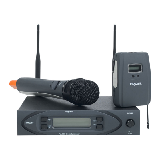
RMW10 Thank you for choosing this PROEL product and for your trust in our brand, synonymous of professionalism, accuracy, high quality and reliability. All our products are CE approved and designed for continuous use in professional systems. 2. Description The RMW10 Wireless Microphone system features 3 units: the RMW10 receiver, WMP handheld transmitter and WHP body pack transmitter. -
Page 18: B) Rear Panel Rmw10
This output recommended for long distance between RMW10 and the mixer. Use a balanced, shielded cable and female XLR connector. 4. 6.3 Jack Mono Unbalanced audio output The unbalanced output should only be used if the RMW10 and the mixer are in close proximity. Use a jack mono 6.3 and a shielded unbalanced cable. 5. VDC Power Connector Connect the power supply cable to the VDC after having connected the plug to the main power supply (220-230Vac). -
Page 19: D) Body Pack Transmitter
RMW10 d) Body Pack Transmitter 1. Display LCD displays: antenna symbol ( when TX and RX are couplet), operating frequency, charge battery level, CHANNEL, GROUP, power transmission (PL), LOCK. 2. CH/ON Press for one second to switch the Transmitter on. The transmitter displays the current frequency and the battery charge level. -
Page 20: Operation
RMW10 4. Operation a) Receiver RMW10 A: Frequency group. B: Channel. C: Mute (symbol is displayed when function mute is activated). D: Selected frequency. E: Transmitter Battery charge level. F: Audio in input level. G: Level of the signal received. -
Page 21: Squelch Control
RMW10 Squelch Control Enter SQUELCH mode by pressing the MENU key 5 times. The SI symbol with the current level value is displayed: Number Squelch threshold 95,0 dB 91,7 dB 88,3 dB 85,0 dB 81,7 dB 78,3 dB 75,0 dB... -
Page 22: Installation
Unbalanced connection: Unbalanced connection with Mono jack RCA connection Connect the antenna, connect the power adaptor to the RMW10 and then to the mains power supply socket Switch on the receiver. Insert the batteries in the transmitter and switch on. -
Page 23: Frequency Table (798.000-827.000Mhz)
RMW10 6. Frequency Table (798.000-827.000MHZ) Group1 Group2 Group3 Group4 Group5 Group6 Group7 Group8 Group9 Group10 Group11 Group12 798.125 798.325 798.525 798.725 798.925 799.125 799.325 799.525 799.725 799.925 800.125 800.325 800.525 800.725 800.925 801.125 801.325 801.525 801.725 801.925 802.125 802.325 802.525 802.725... - Page 24 PROEL S.p.A. pursues a policy of continuous research and development. PROEL S.p.A. reserves the right to modify product circuitry and appearance at any moment, without prior notice. PROEL S.p.A. Via alla Ruenia 37/43 64027 Sant’Omero (Te) – Italy Tel: +39 0861 81241 Fax: +39 0861 887862 info@proelgroup.com...
- Page 25 RMW10...
- Page 26 PROEL S.p.A. (World Headquarters - Factory) Via alla Ruenia 37/43 64027 Sant’Omero (Te) – Italy Tel: +39 0861 81241 Fax: +39 0861 887862 E-mail: info@proelgroup.com www.proelgroup.com...
Need help?
Do you have a question about the RMW10 and is the answer not in the manual?
Questions and answers