Gemini 933 Series Installation And Use Manual
Hide thumbs
Also See for 933 Series:
- Installation and use manual (9 pages) ,
- Installation and use manual (9 pages)
Table of Contents
Advertisement
Quick Links
INSTALLATION CERTIFICATE
The undersigned qualified installer attests having personally fitted the here described vehicle
security system following the manufacturer instructions.
By :
Sold on :
................................................
V
ehicle
:
..........................................................................................................................
GEMINI Technologies S.p.A.
Via Luigi Galvani 12 - 21020 Bodio Lomnago (VA) - Italia
Tel. +39 0332 943211 - Fax +39 0332 948080
Web site: www.gemini-alarm.com
Azienda Certificata ISO 9001
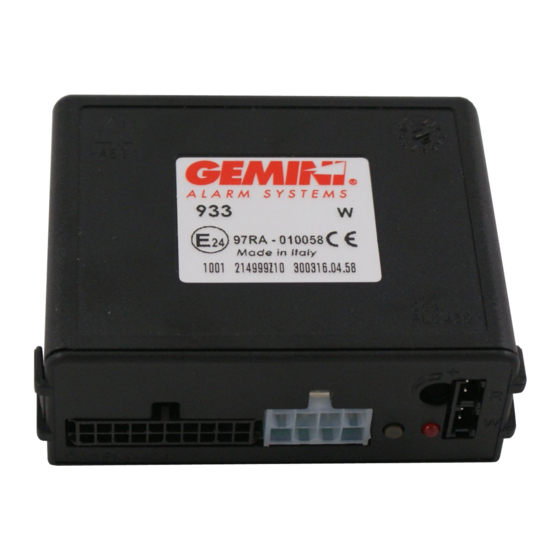
933
T
ype of product
:
932
SERIE 933
INSTALLATION AND
USE MANUAL
Made in Italy
933
932
UK
AC 2784 Rev. 05 - 12/12
Advertisement
Table of Contents

Related Manuals for Gemini 933 Series


Summary of Contents for Gemini 933 Series
- Page 1 ..........ehicle .......................... INSTALLATION AND USE MANUAL GEMINI Technologies S.p.A. Via Luigi Galvani 12 - 21020 Bodio Lomnago (VA) - Italia Tel. +39 0332 943211 - Fax +39 0332 948080 Web site: www.gemini-alarm.com Made in Italy AC 2784 Rev. 05 - 12/12...
-
Page 2: Table Of Contents
PAGE 03 electrical connections etc. will therefore apply to all models. USER MANUAL Before installing, identify your alarm model and refer to it for the correct instructions GEMINI 932: same as 933 without self-powered battery. - OPERATING DESCRIPTION..................PAGE 03 The following signs, intended for the installer or the user, indicate particular functions or connections 2.1 - Complete system arming.................. -
Page 3: System Armed
5“. The guarantee is valid exclusively at authorized Gemini Technologies S.p.A. Service Centers. An alarm event can generate up to alarm cycles of 30” each for each input and for each arming... -
Page 4: Installer Manual
INSTALLER MANUAL 6.0 - COMPLETE ELECTRIC DIAGRAM 5.0 - CONNECTORS TABLES Before carrying out all electrical connections, 5.1 - 20-WAY CONNECTOR disconnect the negative battery terminal and re- POSITION WIRE FUNCTION WIRE COLOUR connect again after Connection - 1 - ----- ----- completion. -
Page 5: Connection For Turn Signals Activation
System arming/disarming and alarm are managed through CAN-BUS line. Therefore only connect the alarm system CAN BUS line to the vehicle CAN line wires (see available diagrams at web-site www.gemini-alarm.com). 7.2 - CONNECTIONS FOR VEHICLES WITH SEPARATE LINES 8.2 -... -
Page 6: Vehicle Code Programming
TEN FLASHES AND A SHORT PAUSE A separate leaflet, included in the alarm packaging, lists all the available vehicles (codes are updated at packaging time). Up-to-date information on supported vehicle models can be found at: www.gemini- alarm.com (privat e area). THREE FLASHES The system has an indicator LED that signals any wrong vehicle code inserted. -
Page 7: 11.0 - System Programming
Disabled With alarm system disarmed, turn ignition key “ON” and touch electronic key to its receptacle. For Gemini only, turn ignition key ----- A lack of power during electrical system maintenance, will not affect the programming. The procedure must be carried out entirely because key rotation disables the selected function and moves to the next one until the programming procedure is completed. -
Page 8: 13.0 - Adding New Devices
13.0 - ADDING NEW DEVICES 14.0 - DELETING PROGRAMMED DEVICES To carry out the operation successfully, make sure the required electrical connections To carry out the operation successfully, make sure the required electrical connections (bonnet push-button and positive under key) are complete. (bonnet push-button and positive under key) are complete. -
Page 9: Ultrasonic Volumetric Protection
15.0 - ULTRASONIC VOLUMETRIC PROTECTION 17.0 - TECHNICAL SPECIFICATIONS 15.1 - CO NNECTION AND POSITIONING Power supply 12 Vdc nsert the WHITE connector in the “W” marked socket and the RED connector in the “R” marked Current absorption @ 12Vdc with system armed and LED flashing 15 mA socket (see figure below).
Need help?
Do you have a question about the 933 Series and is the answer not in the manual?
Questions and answers