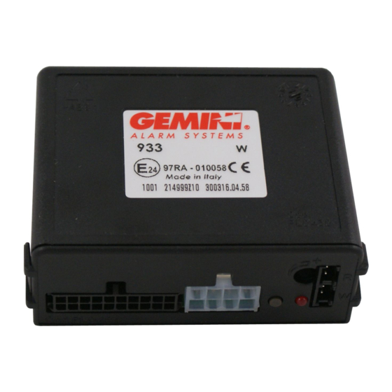
Gemini 933 Series Installation And Use Manual
Hide thumbs
Also See for 933 Series:
- Installation and use manual (9 pages) ,
- Installation and use manual (9 pages)
Table of Contents
Advertisement
Quick Links
INSTALLATION CERTIFICATE
The undersigned qualified installer attests having personally fitted the here described vehicle
security system following the manufacturer instructions.
By :
Sold on :
................................................
V
ehicle
:
..........................................................................................................................
GEMINI Technologies S.r.l.
Via Luigi Galvani 12 - 21020 Bodio Lomnago (VA) - Italy
Tel. +39 0332 943211
www.gemini-alarm.com
ISO 9001 Certified Company
933
T
ype of product
:
932
SERIE 933
INSTALLATION AND
USE MANUAL
Made in Italy
933
932
UK
AC2784/UK Rev.07 - 04/22
Advertisement
Table of Contents

Summary of Contents for Gemini 933 Series
- Page 1 ..........INSTALLATION AND ehicle .......................... USE MANUAL GEMINI Technologies S.r.l. Via Luigi Galvani 12 - 21020 Bodio Lomnago (VA) - Italy Tel. +39 0332 943211 www.gemini-alarm.com AC2784/UK Rev.07 - 04/22 Made in Italy ISO 9001 Certified Company...
-
Page 2: Table Of Contents
1.0 - INTRODUCTORY NOTE TABLE OF CONTENTS Dear Customer, th is manual illustrates the most fully featured alarm system; not all functions, - INTRODUCTORY NOTE.................... PAGE 03 electrical connections etc. will therefore apply to all models. Before installing, identify your alarm USER MANUAL model and refer to it for the correct instructions 932:... -
Page 3: Alarm, Inhibit Time Between Alarms And Alarm Cycles
2.5 - SYSTEM ARMED 3.0 - WASTE ELECTRICAL AND ELECTRONIC EQUIPMENT After the arming delay, the system is fully armed and ready to detect any alarm condition. The LED will The present device falls within the field of application of the current WEEE Directive. The crossed-out start flashing to confirm the armed status. -
Page 4: Installer Manual
INSTALLER MANUAL 5.0 - WIRING DIAGRAM 4.0 - CONNECTOR PINOUTS Before carrying out electrical connections, 20-PIN CONNECTOR disconnect the negative battery terminal and re- POSITION WIRE FUNCTION WIRE COLOUR connect again after - 1 - ----- ----- completion. - 2 - Arm activation signal YELLOW-BLUE Supplied... -
Page 5: Standard Connections
The alarm system can operate in various modes according to the vehicle on which it is installed and 6.1 - STANDARD CONNECTIONS the available connections (see installation specifications in the restricted area of our website: www.gemini-alarm.com LEFT TURN RIGHT TURN... -
Page 6: Vehicle Code Programming
When the last digit is entered, the alarm system “repeats” the entered code. 8.0 - VEHICLE CODE PROGRAMMING f the system is to be managed via CAN-BUS it must be configured according to the vehicle on which it 1 FLASH + is to be installed. -
Page 7: 10.0 - System Programming
“Exclusion” of arm/disarm optical signals Disabled “Exclusion” of arm/disarm acoustic signals Enabled System passive arming Disabled For Gemini only Key OFF/ON Door input - positive Disabled Optical pulse signals (Hazard flashers) Enabled Negative output during alarm cycle (Horn) Disabled For Gemini only Key OFF/ON *ATTENTION: On products Rev.13 and over (see barcode label), “... -
Page 8: 12.0 - Pairing New Devices
12.0 - PAIRING NEW DEVICES 13.0 - DELETE PAIRED DEVICES To carry out the operation successfully, make sure the required electrical connections To carry out the operation successfully, make sure the required electrical connections (bonnet switch and ignition) are properly connected. (bonnet switch and ignition) are properly connected. -
Page 9: Ultrasonic Volumetric Protection
14.0 - ULTRASONIC VOLUMETRIC PROTECTION 16.0 - TECHNICAL SPECIFICATIONS 14.1 - CO NNECTION AND POSITIONING Power supply 12 Vdc nsert the WHITE connector in the “W” marked socket and the RED connector in the “R” marked Current absorption @ 12Vdc with system armed and LED flashing 15 mA socket (see figure below).


Need help?
Do you have a question about the 933 Series and is the answer not in the manual?
Questions and answers