
Related Manuals for Motorola solutions ADVISOR TPG2200 TETRA


Summary of Contents for Motorola solutions ADVISOR TPG2200 TETRA
- Page 1 Mobile Release 19 ADVISOR TPG2200 ™ TETRA Two-way Pager Feature User Guide NOVEMBER 2019 *MN003460A01* MN003460A01-AE © 2019 Motorola Solutions, Inc. All rights reserved...
-
Page 2: Table Of Contents
MN003460A01-AE Contents Contents List of Figures......................7 List of Tables....................... 8 Copyrights........................9 Chapter 1: General Information................10 1.1 Safety Information........................10 1.2 Icon Conventions........................10 1.3 Using this Guide........................11 1.4 Feature and Service Availability.................... 11 Chapter 2: Getting Started..................12 2.1 Product Technical Information....................12 2.2 Before Power On........................ - Page 3 MN003460A01-AE Contents 3.3 Direct Mode Operation......................28 3.3.1 Entering DMO Mode....................29 3.3.2 Selecting DMO Communications Options..............29 3.4 Transmit Inhibit Mode......................29 3.5 Emergency Operations......................30 3.5.1 Emergency Alarm....................30 3.5.2 Exiting Emergency Operations................30 3.6 Graceful Service Degradation Mode..................30 3.6.1 Entering GSDM......................31 3.6.2 Exiting GSDM......................
- Page 4 MN003460A01-AE Contents 4.5.2 Keypad Lock Feature....................40 4.5.2.1 Setting Automatic Keylock Delay............... 40 4.5.2.2 Setting Keylock on Startup.................40 4.5.3 Air Encryption......................40 4.5.3.1 Viewing Air Encryption State..............41 4.5.4 K Validity........................41 4.5.4.1 Verifying K Validity..................41 4.5.5 SCK (Air Interface Encryption Class 2)..............41 4.5.5.1 TMO SCK....................42 4.5.5.2 DMO SCK....................
- Page 5 MN003460A01-AE Contents 4.6.7.2 Setting the Date Manually................49 4.6.7.3 Setting Time Offset..................49 4.6.8 Energy Economy......................50 4.6.8.1 Enabling or Disabling Energy Economy.............50 4.6.9 Transmission Power Class..................50 4.6.9.1 Selecting RF Power................... 50 4.6.10 User Profiles......................51 4.6.10.1 Selecting User Profiles................51 4.6.11 Default Setting.......................
- Page 6 MN003460A01-AE Contents 4.11.4 Starting Crypto Registration...................58 4.11.5 Setting DMO Encryption Mode................58 4.11.6 Setting Encryption Keys for SDS Messages............58 Chapter 5: Features....................60 5.1 Call-Out..........................60 5.1.1 Types of Call-Out Alerts...................60 5.1.2 Call-Out Modes Interaction..................61 5.1.3 Call-Out Service Phases..................61 5.2 Global Positioning System (GPS) Location Service.............. 62 5.2.1 Enhance GPS Performance..................63 5.2.2 Location Report Backlog..................63 5.2.3 GPS Icon........................63...
-
Page 7: List Of Figures
MN003460A01-AE List of Figures List of Figures Figure 1: Opening the SIM Card Door....................14 Figure 2: Opening the SIM Connector Door................... 15 Figure 3: Inserting SIM Card........................15 Figure 4: Closing the SIM Connector Door.....................15 Figure 5: Opening the SIM Card Door....................16 Figure 6: Opening the SIM Connector Door................... -
Page 8: List Of Tables
Table 1: Special Notations........................11 Table 2: Product Technical Information....................12 Table 3: Battery Icons..........................18 Table 4: Advisor TPG2200 TETRA Two-way Pager Controls and Indicators........19 Table 5: Display............................21 Table 6: Colors of the Soft Key Area...................... 22 Table 7: Status Icons..........................23 Table 8: One-Touch Button Features..................... -
Page 9: Copyrights
Motorola Solutions, Inc. Furthermore, the purchase of Motorola Solutions products shall not be deemed to grant either directly or by implication, estoppel or otherwise, any license under the copyrights, patents or patent applications of Motorola Solutions, except for the normal non-exclusive, royalty-free license to use that arises by operation of law in the sale of a product. -
Page 10: Chapter 1: General Information
Regulations. Note that Push-to-Talk (PTT) and in front of the face operating instructions are not applicable for this pager and can be ignored. For a list of Motorola Solutions-approved antennas, batteries, and other accessories, visit the following website: http://www.motorolasolutions.com... -
Page 11: Using This Guide
MN003460A01-AE Chapter 1: General Information NOTICE: NOTICE contains information more important than the surrounding text, such as exceptions or preconditions. They also refer the reader elsewhere for additional information, remind the reader how to complete an action (when it is not part of the current procedure, for instance), or tell the reader where something is on the screen. -
Page 12: Chapter 2: Getting Started
MN003460A01-AE Chapter 2: Getting Started Chapter 2 Getting Started This chapter contains basic information on how to use the radio. Product Technical Information Table 2: Product Technical Information Description Value Maximum Voltage 4.2 V Maximum Current Maximum RF Power 1 or 1.8 W (switchable) Maximum Speaker 8 Ω... -
Page 13: Installing The Battery
MN003460A01-AE Chapter 2: Getting Started 2 Remove the battery cover completely from the radio. To attach the battery cover: NOTICE: Ensure that the Battery Cover Latch is at the Unlock position before attaching the battery cover. 3 Insert the bottom tabs of the battery cover into the slot. 4 Press the battery cover down and lock the battery cover by sliding the Battery Cover Lock key to the right. -
Page 14: Removing The Battery
MN003460A01-AE Chapter 2: Getting Started 2 Press the battery downward until it clicks. 2.2.3 Removing the Battery Prerequisites: Turn off the radio. Procedure: 1 Pull the slot at the top of the battery to release it. 2 Lift out the battery. 2.2.4 Installing the SIM Card Prerequisites:... -
Page 15: Removing The Sim Card
MN003460A01-AE Chapter 2: Getting Started Figure 2: Opening the SIM Connector Door 5 Insert the SIM card into the SIM connector slot, ensuring that the gold contact area is facing down. Figure 3: Inserting SIM Card 6 Close the SIM connector door and slide it to lock (as indicated by the arrow engraved on the SIM connector door). -
Page 16: Figure 5: Opening The Sim Card Door
MN003460A01-AE Chapter 2: Getting Started Figure 5: Opening the SIM Card Door 3 Slide up and unlock the SIM connector door (as indicated by the arrow engraved on the SIM connector door). 4 Flip open the SIM connector door. Figure 6: Opening the SIM Connector Door 5 Remove the SIM card from the SIM connector slot. -
Page 17: Charging The Battery
You can charge a battery separately or attached to a radio. IMPORTANT: Use only Motorola Solutions approved-chargers and cables which provide optimal performance. Using other chargers may fail to fully charge, or reduce the life of the battery. Do not charge the battery in a hazardous area. -
Page 18: Low Battery Indication
MN003460A01-AE Chapter 2: Getting Started Figure 8: Charger Mode Screen Charger Mode Charging: Table 3: Battery Icons Battery Capacity 80%– 0%–5% 5%–15% 15%–25% 25%–40% 40%–60% 60%–80% 100% Battery Charge Progress 80%– 0%–5% 5%–15% 15%–25% 25%–40% 40%–60% 60%–80% 100% 2.2.8 Low Battery Indication The radio indicates low battery level by playing an audible alert when the battery charge falls to a preset level. -
Page 19: Controls And Indicators
Chapter 2: Getting Started Controls and Indicators The simple-to-use controls and indicators of the Advisor TPG2200 TETRA Two-way Pager allows you to quickly read and respond to alerts received on the radio. Table 4: Advisor TPG2200 TETRA Two-way Pager Controls and Indicators... -
Page 20: Powering On The Radio
MN003460A01-AE Chapter 2: Getting Started Annotation Description • Increasing or decreasing the volume • Activating the assigned One-Touch Button feature USB Connector ™ The USB Type-C connector supports charging and programming. NOTICE: When an active KVL device is connected to radio using the USB connector, the radio draws current consumption from the KVL device and start charging. -
Page 21: Unblocking Your Radio
MN003460A01-AE Chapter 2: Getting Started NOTICE: If your radio is using BSI PIN authentication, the radio disables the general PIN authentication. 2.5.1 Unblocking Your Radio If you have entered the incorrect PIN code for more than three times (by default), use the PIN Unblocking Key (PUK) to unblock your radio. -
Page 22: Configurable Idle Screen
MN003460A01-AE Chapter 2: Getting Started The color of the Soft key area changes according to the mode the radio is in. Table 6: Colors of the Soft Key Area Color Mode or State Light blue Normal TMO and DMO Modes Light red Emergency Mode or Disaster Alert Call Olive... -
Page 23: Status Icons
MN003460A01-AE Chapter 2: Getting Started Status Icons Status icons appear when your radio is engaged in certain activities or when you have activated certain features. Depending on your service provider settings, status icons can appear in normal or large size. By default, they are large on the home screen and normal when browsing though the radio menu. - Page 24 MN003460A01-AE Chapter 2: Getting Started Icon Description All Tones Off – Indicates that: • Volume is set to 0 (when Volume Adj. Mode is set to Common). Vibrate Only – Indicates that the radio vibrates to alert you of an incoming message. Vibrate then Ring –...
-
Page 25: Entering Tmo Or Dmo Mode
MN003460A01-AE Chapter 2: Getting Started Icon Description Keys Locked – Indicates that keys are locked. Remote Control – Indicates that the radio is being remotely controlled and some commands are being executed in the background. For example, when the radio is being controlled by special SDS messages or triggered to send a GNSS location re- port. - Page 26 MN003460A01-AE Chapter 2: Getting Started Feature Description Flip Display Rotates the display by 180°. Location Information Pro- Sends a message with the location of the radio to a dedicated ad- tocol (LIP) Report dress. Message Inbox Displays the list of messages in the Inbox. Reset to Default Resets the radio to its default settings.
-
Page 27: Chapter 3: Modes
MN003460A01-AE Modes Chapter 3 Modes This chapter contains information on available modes that the radio can operate in. Trunked Mode Operation Trunked Mode Operation (TMO) requires the switching and management infrastructure. This operation mode enables various data communication types, such as short data service messages. Figure 10: Trunked Mode Operation 3.1.1 Entering TMO Mode... -
Page 28: Entering Local Site Trunking
MN003460A01-AE Chapter 3: Modes 3.2.1 Entering Local Site Trunking When your radio receives a Local Site Trunking indication from the system, the following occurs: • Your radio plays an Entering Local Site Trunking tone. • Display shows the Local Area Service message. •... -
Page 29: Entering Dmo Mode
MN003460A01-AE Chapter 3: Modes 3.3.1 Entering DMO Mode Procedure: To enter the DMO Mode: • From the home screen, press the Menu key. Select Networks → Direct Mode. • From the home screen, press the Menu key. Select Options → Direct Mode. 3.3.2 Selecting DMO Communications Options When and where to use: Helps to communicate with other radio users on the same talkgroup through... -
Page 30: Emergency Operations
MN003460A01-AE Chapter 3: Modes Your radio can still receive and displays any incoming SDS messages. These messages are stored in the Inbox. When no danger to safety exists anymore, for example, when you leave the RF sensitive area, you can deactivate the TXI Mode and the radio returns to standard operation. -
Page 31: Entering Gsdm
MN003460A01-AE Chapter 3: Modes The Graceful Service Degradation Mode (GSDM) provides best effort services when the radio enters a weak signal situation. It provides limited services to users where data circuit operation is no longer available in radio traffic mode. The following services are available in GSDM: •... -
Page 32: Chapter 4: Main Menu
MN003460A01-AE Chapter 4: Main Menu Chapter 4 Main Menu This chapter contains information on items in the main menu. IMPORTANT: Ensure the Menu Configuration is enabled on the CPS to allow the menu settings to be visible on the radio MMI. Scrolling through the Menu Procedure: 1 From the home screen, press the Menu key. -
Page 33: Messages
MN003460A01-AE Chapter 4: Main Menu Menu Icon Description Networks Allows you to select a network. Location Displays location of your radio. Crypto Menu Allows you to manage SIM Card End-to-End Encryption. Messages The messages feature allows you to send and receive text messages. A message can contain up to 1000 characters, depending on your service provider settings. -
Page 34: Receiving New Messages
MN003460A01-AE Chapter 4: Main Menu 4.3.1.1 Receiving New Messages When you receive a new message, your radio displays the New Message icon, an animation, and plays a tone to indicate the new message. Procedure: Select one of the following options: If…... -
Page 35: Immediate Text Message
MN003460A01-AE Chapter 4: Main Menu If… Then… If you want to invoke the forward screen select Forward. with an old message and send it to the NOTICE: You can only forward Individual Short Subscriber Identity (ISSI) this message to the ISSI of the of the dispatcher, dispatcher. -
Page 36: Call-Out (Co) Box
MN003460A01-AE Chapter 4: Main Menu Icon Description Failed Outgoing Message Protected Message Delivery in Progress Protected Message Delivery Accomplished Protected Message Delivery Failed Successful Outgoing Protected Message Failed Outgoing Protected Message 4.3.3 Call-Out (CO) Box CO Box contains incoming and outgoing Call-Out messages. Clicking Select on a Call-Out message headline displays more detailed information on the item. -
Page 37: Sending User-Defined Templates
MN003460A01-AE Chapter 4: Main Menu 4.3.4.1 Sending User-Defined Templates Procedure: 1 From the home screen, press the Menu key. 2 Select Messages → Templates. 4.3.4.2 Managing User-Defined Templates Procedure: 1 From the home screen, press the Menu key. 2 Select Messages → Templates. 4.3.5 Predefined Templates Predefined message templates are programmed into your radio. -
Page 38: Sending Status Messages
MN003460A01-AE Chapter 4: Main Menu 2 Select Messages → Send Status. 4.3.6.2 Sending Status Messages You can send status messages to either a selected talkgroup or a programmed private number. Only one option can be enabled at a time. Prerequisites: •... -
Page 39: Setting Man Down
For easier localization of the radio, visual and audible indications are started until they are deactivated. To exit Man Down, exit the Emergency Mode by pressing and holding the Exit soft key. CAUTION: Use only Motorola Solutions predefined tones when Man Down is activated. 4.4.1... -
Page 40: Changing Pin Codes
MN003460A01-AE Chapter 4: Main Menu 4.5.1.2 Changing PIN Codes NOTICE: This feature is only available when enabled by your service provider. Procedure: 1 Select Security → Change Code. 2 Radio prompts for the Old Code. NOTICE: By default the PIN code are all zeros (depending on the length of the PIN code). -
Page 41: Viewing Air Encryption State
MN003460A01-AE Chapter 4: Main Menu If configured by your service provider, the radio plays a sound and displays Call & Data Not Encrypted when encryption is on and you receive a clear call (unencrypted). This feature provides service confidentiality between you and the system. In the TMO Mode, when Air Encryption is enabled on your radio but cannot be supported due to an infrastructure failure, the following icon appears on the display: . -
Page 42: Tmo Sck
MN003460A01-AE Chapter 4: Main Menu 4.5.5.1 TMO SCK Your service provider can enable SCKs in TMO. The SCKs used in TMO are called TMSCKs. 4.5.5.1.1 Verifying TMSCK Validity When and where to use: To ensure that the TMSCKs in the radio are valid and can be used for the air interface encryption. -
Page 43: Covert Mode
MN003460A01-AE Chapter 4: Main Menu 4 Radio displays Change to version. 5 Select one of the following options: • Yes – To change the key. Your radio displays Key version changed. • No – To leave the key. Your radio displays Code Not Changed. 4.5.6 Covert Mode NOTICE: This feature is a selling feature. -
Page 44: Sds Remote Control
MN003460A01-AE Chapter 4: Main Menu The following tasks can be assigned remotely to a radio: Play loud tone until user interaction The radio plays a loud tone as in the Man Down feature until you unlock the keypad (if needed) and press the appropriate soft key labeled Exit. -
Page 45: Setting Default Vibrate
MN003460A01-AE Chapter 4: Main Menu 4.6.1.1 Setting Default Vibrate Procedure: 1 From the home screen, press the Menu key. 2 Select Setup → Vibrate. 3 Select one of the following options: • Vibe then Ring • Vibe Only • Ring Only 4.6.2 Set Volume This menu item allows you to adjust the tone volumes. -
Page 46: Tones
MN003460A01-AE Chapter 4: Main Menu 4.6.4.1.1 Setting Audio Profiles When and where to use: To adjust the audio parameters of the radio in its current operating environment. Procedure: 1 From the home screen, press the Menu key. 2 Select Setup → Audio → Audio Profile. 3 Select a required profile. -
Page 47: User Imported Tones
MN003460A01-AE Chapter 4: Main Menu 4.6.5.3 User Imported Tones You can import up to eight .wav files as new alert tones, and also remove the imported tones through CPS. For more information about User Imported Tones and CPS, contact your service provider. 4.6.6 Display This menu item allows you to adjust your radio display settings. -
Page 48: Setting Backlight
MN003460A01-AE Chapter 4: Main Menu • Auto – Automatically displays the screen saver when the radio is inactive for a pre- determined period. • Disabled – Disables the screen saver. • Text – To set the text on the screen saver when this feature is activated. 4.6.6.4 Setting Backlight Procedure:... -
Page 49: Time And Date
MN003460A01-AE Chapter 4: Main Menu 4.6.7 Time and Date This sub-menu controls the displayed time and date on the home screen. NOTICE: If the Home Display Text Message feature is enabled, Home Mode Display Text may cover time and date, depending on the Configurable Idle Screen settings. Infrastructure synchronizes the time and date. -
Page 50: Energy Economy
MN003460A01-AE Chapter 4: Main Menu 4.6.8 Energy Economy Energy Economy (EE) is a mode of operation to save battery life. Your radio does not monitor all downlink time slots of the Main Control Channel. If the radio is in the charger, Energy Economy mode is not needed. -
Page 51: User Profiles
MN003460A01-AE Chapter 4: Main Menu 4.6.10 User Profiles This menu item allows you to select a predefined user profile. 4.6.10.1 Selecting User Profiles Prior to any configuration, the first user profile is selected by default. When and where to use: Procedure: 1 From the home screen, press the Menu key. -
Page 52: Shortcuts
MN003460A01-AE Chapter 4: Main Menu NOTICE: OPTA information is optional. • Battery Info – displays battery charge in %. • Storage Info – displays the amount of free and total space available in the internal radio memory. Shortcuts This sub-menu allows you to set up shortcuts to access frequently used menu items. 4.8.1 Creating Menu Shortcuts When and where to use: To assign a shortcut for the menu item. -
Page 53: Networks
MN003460A01-AE Chapter 4: Main Menu Networks This menu item allows you to switch between the radio operation modes. 4.9.1 Selecting Network Operation Mode Procedure: 1 From the home screen, press the Menu key. 2 Select Networks. 3 Select one of the following options: •... -
Page 54: Using Any Network Registration
MN003460A01-AE Chapter 4: Main Menu 4.9.2.3 Using Any Network Registration When and where to use: Your radio has lost its home network coverage and wants to increase the number of networks it can scan and register. Procedure: 1 From the home screen, press the Menu key. 2 Select Networks →... -
Page 55: Using Any Tg Net Registration
MN003460A01-AE Chapter 4: Main Menu 3 Select the required network from the list. 4.9.3.4 Using Any TG Net Registration When and where to use: Your radio has lost its network coverage and wants to increase the number of networks it can scan and register. If the talkgroup selected is an Any Net talkgroup, this menu displays all networks allowed for scanning and registration. -
Page 56: Viewing Testpage
MN003460A01-AE Chapter 4: Main Menu 4.10.3 Viewing Testpage Procedure: 1 From the home screen, press the Menu key. 2 Select Location → Testpage. 3 Select one of the following options: • Position – Displays detailed information on your radio current position: time, N (latitude), E (longitude), H (height), Sats Used (a number of tracked satellites), B (bearing), HS (horizontal speed), LC (level of confidence). -
Page 57: Viewing Backlog Reports
MN003460A01-AE Chapter 4: Main Menu 4.10.5.2 Viewing Backlog Reports Procedure: 1 From the home screen, press the Menu key. 2 Select Location → Backlog → Reports. The radio displays the number of backlog reports stored. 4.10.5.3 Deleting All Backlog Reports Procedure: 1 From the home screen, press the Menu key. -
Page 58: Setting Opta Filter
MN003460A01-AE Chapter 4: Main Menu 4.11.3 Setting OPTA Filter When and where to use: Use this menu item to define which characters are masked when the OPTA name is displayed. Procedure: 1 From the home screen, press the Menu key. 2 Select Crypto Menu →... - Page 59 MN003460A01-AE Chapter 4: Main Menu • Group Key...
-
Page 60: Chapter 5: Features
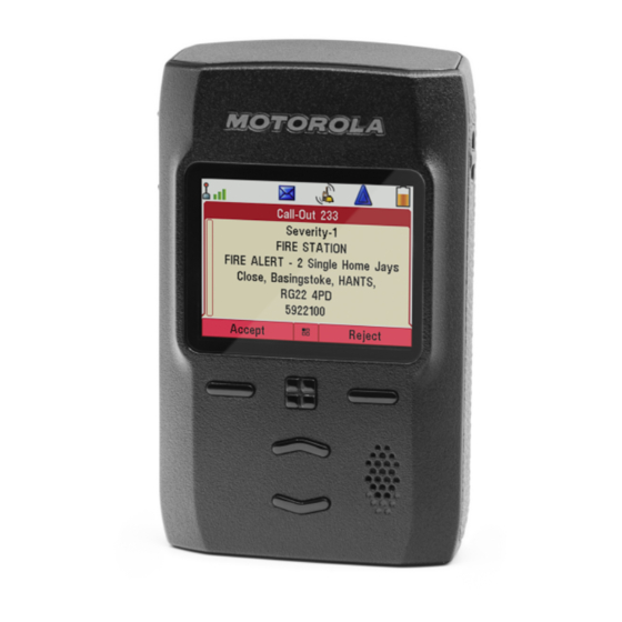
MN003460A01-AE Chapter 5: Features Chapter 5 Features Call-Out This feature allows you to receive Call-Out alerts. On receiving the Call-Out messages, the radio interrupts current services and attends to the Call-Out alert without any further delay. After the Call-Out is cleared by the dispatcher, the radio exits Call-Out mode and reverts to normal mode. The time-stamp on the Call-Out alert indicates the time and date when the Call-Out is received. -
Page 61: Call-Out Modes Interaction
MN003460A01-AE Chapter 5: Features Storm Plan An alert message that is sent by a dispatcher to a group of radios. To raise its reliability, it is sent several times. You are not able to respond to the Call-Out alert and any key press takes you to the information phase. -
Page 62: Global Positioning System (Gps) Location Service
MN003460A01-AE Chapter 5: Features Missed Call-Out Reminder Phase A Call-Out is cleared without any user input. The radio will display the missed Call-Out with the following options: • Messages, or • Exit. NOTICE: You can choose to dismiss the reminder phase instead of reading the missed Call- Out message. -
Page 63: Enhance Gps Performance
MN003460A01-AE Chapter 5: Features The radio can be configured to give audio-visual notifications upon sending the Location Reports. Depending on the radio settings, viewing the radio position and the status of the visible satellites is available. The position may consist of longitude and latitude, UK, or Irish grid coordinates. 5.2.1 Enhance GPS Performance Sometimes the GPS feature is unable to complete a location calculation successfully. -
Page 64: Different Location Displays
MN003460A01-AE Chapter 5: Features Depending on the current GPS state, the icon can be solid – GPS has a fix, or blinking – GPS is searching for a fix. The blinking GPS icon can be disabled/enabled by your service provider. 5.2.4 Different Location Displays Table 13: Different Location Displays... -
Page 65: Gps Accuracy
MN003460A01-AE Chapter 5: Features 5.2.5 GPS Accuracy The GPS Location Service accuracy depends on the GPS coverage and the selected accuracy mode. In good GPS coverage (at least -137 dBm or in open sky), the location accuracy presents as follows: •... -
Page 66: Rms Icons
MN003460A01-AE Chapter 5: Features RMS free text messages and incoming and outgoing RMS statuses are stored in the RMS Box. Its capacity is maximum one hundred entries for incoming and outgoing RMS messages. If the RMS Box is full, any new incoming or outgoing RMS message overwrites the oldest message (received or sent). The latest RMS free text is kept on the home screen until the next power cycle. -
Page 67: Terminal Permanent Disable
Disable your service provider cannot enable your radio. It is recommended to Permanent Disable your radio only when you do not expect to recover it. If it is recovered then a Permanent Disable radio can be reactivated by returning it to Motorola Solutions. Terminal Temporary Disable or Enable Your radio is provided with a feature that allows your service provider to disable it temporarily in case it is stolen. -
Page 68: Appendix A: Tones
MN003460A01-AE Appendix A: Tones Appendix A Tones NOTICE: The radio has two tone packs which are the default Classic Tones and New Tones. Your service provider decides which tone pack is enabled. To listen to the audio signal tones samples, click Table 17: Radio Tones New Tone Classic Tone... -
Page 69: Appendix B: Led Indications
MN003460A01-AE LED Indications Appendix B LED Indications LED Patterns The Message LED indicates Call Out alert or message receiving statuses. The Status LED indicates other general statuses. Each user profile has preprogrammed LED patterns for the following indications: • Call Out Alert •... - Page 70 MN003460A01-AE Appendix B: LED Indications Indication Status Blinking green Battery charged at 90% Solid red Rapid or trickle charge Blinking red Faulty or invalid battery Blinking orange Battery is waiting to charge NOTICE: When you charge your radio in a multi-unit charger, the LED Power Indicator of the radio indicates the charge status of the battery.
-
Page 71: Appendix C: Troubleshooting
MN003460A01-AE Troubleshooting Appendix C Troubleshooting Your radio displays the following messages: Table 21: Displayed Messages Message Message Description Attachment Failed Your radio could not perform talkgroup attachment. It keeps on trying. If it does not succeed, try another talk- group. Authenticate Failure Your radio could not register on an authenticated system (for example, the Authentication Key is incorrect, or au-... - Page 72 MN003460A01-AE Appendix C: Troubleshooting Message Message Description No Service Your radio is out of coverage. Not Allowed To Transmit You are not allowed to send a text message or a status message. Single TalkGroup Only There is only one programmed entry in the scrolling list. Overheating, Please Turn Your radio turns off.
-
Page 73: Appendix D: Maintenance
Extending Battery Life A battery is an expendable part and may need replacing during the life of the radio. To ensure maximum service life of your radio, always replace the battery with a genuine Motorola Solutions replacement. Battery Charging Temperature If, during charging, the temperature is out of range, the battery might not be fully charged since the charging is temporarily stopped until the temperature becomes suitable.
Need help?
Do you have a question about the ADVISOR TPG2200 TETRA and is the answer not in the manual?
Questions and answers