Advertisement
Available languages
Available languages
PowPak
Fixture Controls
®
Installation
Part of the Energi TriPak
Family
®
041485
Please read before installing.
Rev. A
04/2015
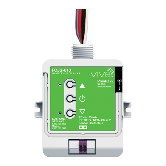
FCJ-010
120 – 277 V~ 50 / 60 Hz 1 A switching
0–10 V-
6 mA sink/source
FCJ-ECO
120 – 277 V~ 50 / 60 Hz 1A switching
Lutron
®
14 V- 6 mA
EcoSystem
®
PowPak
Wireless Fixture Control
®
UL 2043 Plenum Rated
Controls up to 3 ballasts or drivers (IEC 60929 Annex E.2 requires each ballast or
driver to limit the sink/source current draw to 2.0 mA maximum).
Provides IEC SELV / NECR Class 2, 12 V-, 25 mA to a PowPakR fixture sensor
(FC-SENSOR or FC-VSENSOR).
Important Notes:
• For installation by a qualified electrician in accordance with all local and
national electrical codes.
• Use copper conductors only.
• Check to see that the device type and rating is suitable for the application.
• DO NOT install if product has any visible damage.
• If moisture or condensation is evident, allow the product to dry completely
before installation.
• Operate between 32 °F and 104 °F (0 °C and 40 °C), ambient.
• 0% to 90% humidity, non-condensing.
• For indoor use only.
PowPakR Fixture
Control
Install the fixture control directly to a fixture or
on a junction box nearest to the fixture. Install
the sensor on the ceiling near the fixture to
optimize coverage in the desired area.
Sensor
30 ft (9 m)
Fixture
maximum
Control
Pico
®
wireless
control
Wireless sensors
and controls must
be located within
60 ft (18 m) line of sight,
or 30 ft (9 m), through walls, of
the associated control module.
Default Functionality
Wireless Controls: All lights
On: 100% ; Favorite: 50%; Off: 0%
Fixture Controls
Auto On level: FC-SENSOR only
(not applicable for FC-VSENSOR)
Varies with ambient light level when occupancy is triggered
(e.g., 100% for a dark room, 10% for a bright room).
Timeout period: 15 minutes
For more information, see
www.lutron.com/TechnicalDocumentLibrary/369866.pdf
Lutron Electronics Co., Inc. 7200 Suter Road
Coopersburg, PA 18036-1299 USA
Required Components
For each fixture, you will need:
One Fixture Control
At least one of these transmitters (22 total allowed)
PIR Lens
Raise
Load
Laser
Status
Detection
Daylight Lens
LED
Toggle
+
Lower
PowPakR Fixture Sensor
PowPakR Wireless Fixture Control
(FC-SENSOR or
(FCJ-010 or FCJ-ECO)
FC-VSENSOR)
(1 maximum)
Start Here
Install Fixture Control and Optional Fixture Sensor
1
Suggested Installation Location: Close to the Fixture / Troffer.
WARNING! Shock Hazard. May result in serious injury or death.
Turn off power at circuit breaker before installing the unit.
The fixture control can be installed on a fixture/troffer, junction box or marshalling box using the conduit nut
(provided) or with mounting screws (not provided). Please consult local and national electric codes for proper
installation.
A Ideally, mount the sensor to the ceiling tile close to the fixture using the wireform or using the adhesive strip
(included). The two communication wires from the sensor attach to the fixture control stab-in connectors. The
wires are interchangeable to eliminate miswiring.
B Once installed, energize the control module. The fixture will turn on.
Hot (Black)
Green/Yellow
Neutral
Neutral (White)
Switched Hot (Red)
+
Violet (both FCJ-010 and FCJ-ECO)
–
Gray (FCJ-010) / Violet (FCJ-ECO)
Fixture/Troffer
or Junction
Box
1/2 in (21 mm) Knockout Opening
Conduit Nut
Important Note: To optimize RF performance of the product:
– Keep the lamp wiring as short as possible to reduce the radiation from
the lamp wires.
– Keep the lamp wiring as far as possible from the PowPakR Wireless
Fixture Control mounting location.
See the Troubleshooting section for more details.
From back
of sensor
Maximize Distance
Notes:
1. Control wires (Violet/Gray for FCJ-010 or Violet/Violet for FCJ-ECO) can
be run as either Class 1 or Class 2.
2. If hanging pendant fixtures the maximum wire length between fixture
sensor and fixture control is 12 ft (3.7 m). Sensor should be mounted no
more than 2 ft (0.6 m) from the fixture.
3. To install unit inside a junction box, please see Application Note 423 on
www.lutron.com
Technical Assistance | 1.800.523.9466 USA, Canada, and the Caribbean | +44.(0)20.7702.0657 Europe | +1.610.282.3800 Others | www.lutron.com
Notes:
1. Fixture control can be used
without a fixture sensor as long
as at least one Radio Powr
SavrT sensor or PicoR wireless
control is used.
2. Only one fixture control can be
used per fixture sensor, and
only one fixture sensor can be
used per fixture control.
Radio Powr SavrT
Radio Powr SavrT
Occupancy/Vacancy
Daylight Sensor
Sensor
(1 maximum)
(10 maximum)
Associate Transmitters to Fixture Control
2
Before beginning this step, make sure that there are no other fixture controls being set up in the building which
are currently in association mode. It is possible that wireless transmitters from other systems can be incorrectly
associated to this module.
A
Initiate association mode on the fixture control by shining a green laser pointer (by others) at the laser
detection hole on the sensor until the load attached to the control module starts flashing (every 2 seconds).
Alternatively, press and hold the Toggle button " " for 6 seconds on the fixture control to initiate
association mode.
Note: Multiple fixture controls can be placed into association mode by repeating one of the two above methods for the next
fixture control prior to moving to Step 2B.
Fixture Earth
NEU
HOT
Ballast / Driver
+
–
Green laser specifications:
• Wave output: constant
• Wavelength: 532 nm
• Output power: 5 mW
Note: The fixture control will automatically exit
association mode 10 minutes after the last activity.
B Hold the indicated button on each transmitter for 6 seconds. The fixture will flash to show that wireless
transmitters have been associated. Alternatively, for Radio Powr SavrT occupancy/vacancy and daylight
sensors, the green laser pointer can be used. See Application Note #407 on www.lutron.com for more
information.
To associate another transmitter, repeat steps 2A and 2B.
PowPakR Fixture Control Wiring
PowPakR Fixture Control Knockout
Lamp Wiring
4. The fixture control needs to be accessible for some programming steps.
Record where it is mounted so that it can be easily located later.
5. When using a Radio Powr SavrT daylight sensor in conjunction with both
a PowPakR wireless fixture control and PowPakR fixture sensor, the
Radio Powr SavrT daylight sensor will provide the daylighting input to the
control module, and the PowPakR fixture sensor daylighting input will be
ignored.
FCJ-010: At least one 0 – 10 V Fluorescent Ballast or LED Driver
FCJ-ECO: At least one Lutron
EcoSystem
®
Consult the fixture installation guide for fixture wiring.
+
PicoR Wireless
Control
6 mA maximum for the control lines. Switches up to 1 A total
(10 maximum)
(or maximum 3 ballasts or drivers). May be pre-installed in fixture.
Hot (Black)
Laser Detection
Neutral
OR
Link
Test
6. When using a Radio Powr SavrT occupancy sensor in conjunction with
both a PowPakR wireless fixture control and PowPakR fixture sensor,
occupancy data from both sensors is used; either one detecting
occupancy will turn the lights on, and the lights turn off only when both
sensors have gone vacant (no longer detect occupancy).
7. For more information on the PowPakR fixture sensor, see: Document
369866 or 048556 on www.lutron.com
For FC-SENSOR and FC-VSENSOR installation guide visit www.lutron.com
Ballast or LED Driver
®
+
–
Advertisement
Table of Contents

Related Manuals for Lutron Electronics PowPak FCJ-010


Summary of Contents for Lutron Electronics PowPak FCJ-010
- Page 1 3. To install unit inside a junction box, please see Application Note 423 on For more information, see ignored. 369866 or 048556 on www.lutron.com www.lutron.com www.lutron.com/TechnicalDocumentLibrary/369866.pdf For FC-SENSOR and FC-VSENSOR installation guide visit www.lutron.com Lutron Electronics Co., Inc. 7200 Suter Road Coopersburg, PA 18036-1299 USA...
-
Page 2: Reset Factory Defaults
• Connect the equipment into an outlet on a circuit different from that to which the receiver is connected. )Lutron, Lutron, Pico, PowPak, EcoSystem, and Energi TriPak are registered trademarks and Radio Powr Savr is a trademark of Lutron Electronics Co., Inc. - Page 3 PowPakR será ignorada. consulte: Documentos 369866 o 048556 en www.lutron.com www.lutron.com/TechnicalDocumentLibrary/369866.pdf Para obtener la guía de instalación del FC-SENSOR y FC-VSENSOR visite www.lutron.com Lutron Electronics Co., Inc.7200 Suter Road Coopersburg, PA 18036-1299 E.U.A.
-
Page 4: Solución De Problemas
• Conectar el equipo a un tomacorriente que corresponda a un circuito diferente de aquel al cual está conectado el receptor. )Lutron, Lutron, Pico, PowPak, EcoSystem y Energi TriPak son marcas comerciales registradas y Radio Powr Savr es una marca comercial de Lutron Electronics Co., Inc. - Page 5 Document 369866 ou 048556 sur www.lutron.com PowPakR sont ignorées. Pour le guide d'installation du FC-SENSOR et FC-VSENSOR consultez www.lutron.com Lutron Electronics Co., Inc. 7200 Suter Road, Coopersburg, PA 18036-1299, États-Unis...
-
Page 6: Restaurer Les Réglages D'usine
• Connectez l’équipement à une prise électrique se trouvant sur un circuit différent de celui où le récepteur est connecté. )Lutron, Lutron, Pico, PowPak, EcoSystem et Energi TriPak sont des marques déposées et Radio Powr Savr est une marque de Lutron Electronics Co., Inc.
Need help?
Do you have a question about the PowPak FCJ-010 and is the answer not in the manual?
Questions and answers