Table of Contents
Advertisement
Quick Links
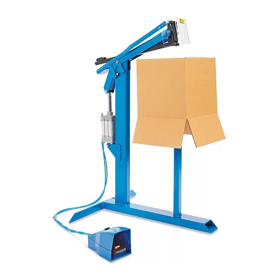
π H-3070
KIHLBERG PNEUMATIC
BOTTOM STAPLER
LOAdINg mAgAzINE
NOTE: Always use Josef Kihlberg original staples.
The correct designation is marked on each
stapling head.
1.
Pull the pusher (1) back and lift up the magazine
breech (2). (See Figure 1)
1
2. Insert staple strips (3) from the rear. (See Figure 1)
WARNINg! do not overload the magazine, as
this may damage the pusher when the breech
is closed.
Never release the pusher directly from the rear
when the magazine is empty; carefully guide it
forward by hand.
PAGE 1 OF 4
1-800-295-5510
uline.com
PREPARATION
Figure 1
2
3
AdJUSTINg ANVIL
Though the tool is tested carefully before delivery, it may
have seen rough treatment during transport and the
anvil may therefore have to be adjusted.
1.
Slide down a staple (4) by hand until the staple legs
are visible. (See Figure 2)
2. Move the staple towards the anvil (5) until the
staple legs hit the anvil symmetrically. (See Figure 2)
3. If necessary, loosen the screw (6) and center the
anvil to the staple. Lock screw after adjusting.
(See Figure 2)
4. Make a test-stapling in a piece of carton. When
everything is in order, you can start using the tool.
Figure 2
4
5
6
0412 IH-3070
Advertisement
Table of Contents

Related Manuals for U-Line H-3070


Summary of Contents for U-Line H-3070
- Page 1 π H-3070 1-800-295-5510 uline.com KIHLBERG PNEUMATIC BOTTOM STAPLER PREPARATION LOAdINg mAgAzINE AdJUSTINg ANVIL NOTE: Always use Josef Kihlberg original staples. Though the tool is tested carefully before delivery, it may The correct designation is marked on each have seen rough treatment during transport and the anvil may therefore have to be adjusted.
- Page 2 PREPARATION CONTINUEd NOTE: The stapler does not need lubrication. Connect and adjust the air pressure to 5,0 bars Figure 3 (72 psi) for proper functioning. STAPLINg gAP • Maximum: 100 mm • Preset: 95 mm AdJUSTINg STAPLINg gAP Disconnect the air supply 2.
- Page 3 mAINTENANCE CONTINUEd ChANgINg RETURN SPRINg ChANgINg RETURN SPRINg Loosen both screws (16). (See Figure 6) Loosen screw (25). (See Figure 8) Figure 6 Figure 8 2. Split the head (20) and exchange the springs (17). 3. Assemble in reverse order. ChANgINg dRIVER 2.
- Page 4 SAfETy • Never use oxygen, combustible gases, CO , steam • The stapler and its hose are equipped with a or high pressure gas tanks as power sources for the connection nipple that automatically exhausts air this tool. The tool could explode and cause serious from the tool after it has been disconnected.
Need help?
Do you have a question about the H-3070 and is the answer not in the manual?
Questions and answers