
Related Manuals for IXXAT iPC-I 165


Summary of Contents for IXXAT iPC-I 165
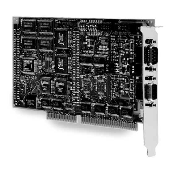
- Page 1 Hardware Manual iPC-I 165 Intelligent PC/CAN Interface The expert for industrial and automotive communication...
- Page 2 Internet: www.ixxat.de Internet: www.ixxat.com e-Mail: info@ixxat.de e-Mail: sales@ixxat.com Support In case of unsolvable problems with this product or other IXXAT products please contact IXXAT in written form by: Fax: +49 (0)7 51 / 5 61 46-29 e-Mail: support@ixxat.de Copyright Duplication (copying, printing, microfilm or other forms) and the electronic distribution of this document is only allowed with explicit permission of IXXAT Automation GmbH.
-
Page 3: Table Of Contents
3.2.2 Serial RS232 interface .............15 Appendix..................16 Appendix A ................16 Technical Data ................16 EMC test................... 16 Appendix B................17 Delivery settings ..............17 Appendix C................18 Supply sources for data sheets..........18 Copyright IXXAT Automation GmbH iPC-I 165 - Manual, Version 2.3... -
Page 5: Introduction
The aim of this manual is to help you familiarize yourself with your interface, also referred to in the following as iPC-I 165. Please read this manual before begin- ning with the installation. Features •... -
Page 6: Block Diagram
AD 0..15 32 kB 1. CAN 2. CAN Controller Controller AD 0..15 82C200/82527 82C200/82527 Microcontroller RESET SAB C165LM CAN Bus- CAN Bus- Interface Interface RS232 CAN High CAN Bus CAN Low Copyright IXXAT Automation GmbH iPC-I 165 - Manual, Version 2.3... -
Page 7: Installation
(7) Close the PC; the hardware installation is now completed. Software installation To operate the interface, a driver is required. For the installation of the CAN driver VCI please read the VCI installation manual. Copyright IXXAT Automation GmbH iPC-I 165 - Manual, Version 2.3... -
Page 8: Configuration
The diagram Fig. 3-1 shows the positions of the plugs and jumpers on the inter- face board. Ground pin First CAN line Second CAN line Serial interface Fig. 3-1: iPC-I 165 interface board Copyright IXXAT Automation GmbH iPC-I 165 - Manual, Version 2.3... -
Page 9: Setting The Base Address
The required interrupt is set with the jumper board JP1 by connecting the jumper pair belonging to the requested IRQ. Only one interrupt may be selected for the iPC-I 165! If no interrupt is required, no pin may be bridged on JP1. The factory setting of the interface is IRQ 5. -
Page 10: Bit Access Mode
By setting the switch 5 of DIP switch SW1 to OFF, the 16 bit access for the iPC-I 165 can be activated. Then iPC-I 165 will be accessed with 16 bit bus cycles from the ISA bus. If the 16 bit access is switched off the interface is accessed with 8 bit wide bus cycles. -
Page 11: Bootstrap Loader
Switch 8 of DIP switch SW1 must remain in OFF position, otherwise the board will try to execute program code on the EEPROM (which is not available anymore at the actual version of the iPC-I 165). If the DIP switch SW3 is assembled, only the switch 2 (interrupt level) may be changed by the user. -
Page 12: Bus Termination Resistors
One (common) or two independent bus connectors according to ISO/IS 11898 can be installed on the iPC-I 165. The signals of the 1st bus connector are pro- vided by the 9 pole sub-D plug/sleeve. If two independent bus connectors are installed the signals for the CAN bus of the 2nd bus connector are provided by the connector JP19. - Page 13 GND (via JP6) CAN High VCC (via JP5) With electrically isolated bus transceivers the signals GND and VCC are also elec- trically isolated from the GND and VCC signals of the interface. Copyright IXXAT Automation GmbH iPC-I 165 - Manual, Version 2.3...
- Page 14 CAN high of X9 (X11) are connected to X4/X5 (JP19) via the protection circuit. The pin assignment of the SUB D9 connector/sleeve connected to JP19 is equal to the pin assignment of the first CAN line (see page before). Copyright IXXAT Automation GmbH iPC-I 165 - Manual, Version 2.3...
-
Page 15: Serial Rs232 Interface
A serial interface according to RS232C standard might be available on the iPC-I 165. The signals TxD, RxD and GND are on connector X3. The interface is accessed by the integrated serial interface of the SAB C165 on the port pins P3.10 and P3.11. -
Page 16: Appendix
DIN EN 50082-2:02.96 EMC test The PC/CAN interface iPC-I 165 has to be used only in a CE compliant PC. The case of the PC should be sealed up against high frequency electrical noise. Use only shielded cables for connecting the PC/CAN interface to the CAN bus and connect the cable shield to the connector case. -
Page 17: Delivery Settings
Appendix Appendix B Delivery settings In the following the configuration of the iPC-I 165 is stated as it is at the time of delivery. In case of special versions of the interface settings can be different. base address D000h SW1-1... -
Page 18: Supply Sources For Data Sheets
Appendix Appendix C Supply sources for data sheets Dual-port-RAM IDT 71342LA: http://www.idt.com CAN controller Philips SJA1000: http://www.philips-semiconductors.com CAN controller Intel 82527: http:/www.intel.com Microcontroller Infineon SAB C165: http://www.infineon.com Copyright IXXAT Automation GmbH iPC-I 165 - Manual, Version 2.3...
Need help?
Do you have a question about the iPC-I 165 and is the answer not in the manual?
Questions and answers