
Subscribe to Our Youtube Channel
Related Manuals for Air Weigh LoadMaxx Plus


Summary of Contents for Air Weigh LoadMaxx Plus
- Page 1 LoadMaxx Plus & QuickLoad Plus Installation Guide For Trailers with Mechanical Suspensions Air-Weigh Customer Support: 888-459-3247 PN 901-0171-000 R0...
-
Page 2: Table Of Contents
Table of Contents About the Air-Weigh Trailer Scale for Mechanical Suspensions..1 Installation Overview................1 Tools Required..................2 Mounting the Scale...................3 Mounting Flush to the Trailer..............4 Mounting with a Van or a Frame Rail Bracket........5 Connecting Power to the Scale...............6 Power Cable Installation Guide.............6 Connecting Power with the ABS Connector..........7 Connecting Power to the Junction Box..........8 Alarm Installation..................8... -
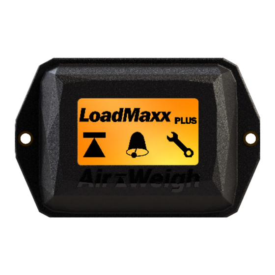
Page 3: About The Air-Weigh Trailer Scale For Mechanical Suspensions
Air-Weigh Trailer Scales for mechanical suspensions accurately measures real-time, on-the-ground weights. The leaf spring scale is currently designed for tandem and tri-axle trailers. The LoadMaxx Plus version enables drivers to view steer, drive, trailer, GVW, and net payload on any LoadMaxx equipped tractor. Air-Weigh App Download the Air-Weigh app and view weight data on any smart device. -
Page 4: Tools Required
Note: Use the bracket template that has been provided with your trailer kit and follow directions on the template to double check that the bracket will fit. Note: Bracket is installed on the front and rear axles for tandem trailers and on the center and rear axles for tri-axle trailers. Tools Required You will need the following tools to install the trailer scale and deflection sensors:... -
Page 5: Mounting The Scale
Mounting the Scale There are three ways you can mount the trailer scale: • Flush mounted to the trailer frame itself • Using a Van bracket • Using a Frame Rail bracket Flush Mount Van Bracket Frame Rail Bracket Choose the mounting method that will work the best for your trailer configuration. -
Page 6: Mounting Flush To The Trailer
Mounting Flush to the Trailer A flush mounted scale is mounted directly to the side of the trailer. 1. Determine the best location to mount the scale. This should be a flat area of the trailer, thin enough to make drilling possible and accessible from both front and back. -
Page 7: Mounting With A Van Or A Frame Rail Bracket
Mounting with a Van or a Frame Rail Bracket 1. Determine the best location to mount the scale. For the Van Bracket, the bracket screws should be mounted on a ledge, and the scale itself should hang off the ledge with no obstacles blocking it. -
Page 8: Connecting Power To The Scale
Connecting Power to the Scale You can connect the trailer scale to the trailer’s power either through the ABS brake harness, through the junction box, or directly through the lighting harness. All methods are equally effective regardless of your trailer setup; choose the method that is most convenient. Note: If using lighting harness for power, the lights need to be on in order for the trailer scale to have power. -
Page 9: Connecting Power With The Abs Connector
Connecting Power with the ABS Connector Connecting the T-Breakout to the Power Cable North American trailer manufacturers use one of two standard connectors to connect the trailer’s wiring harness to the ABS brake system: USA Brand, which uses a 6-pin plug, or Sealco, which uses a 5-pin plug. Air-Weigh provides T-breakout connectors that do not require splicing or soldering and do not interrupt power to the ABS system for each of these connector types. -
Page 10: Connecting Power To The Junction Box
Connecting Power to a Junction Box 1. Starting at the 7-way connector at the front of the trailer, follow the wiring harness until you reach/find the junction box. Remove the cover of the junction box to expose the wiring. Find the blue ABS power wire. -
Page 11: Welding The Deflection Sensor Brackets
Welding the Deflection Sensor Brackets Note: Air-Weigh takes no responsibility for damage or failure of the trailer axle due to improper welding or failure to follow these instructions. 1. Find and mark the center of the forward face on the trailer axle(s), front and rear for tandems or middle and rear for tri- axles. - Page 12 3. Using a permanent marker, mark the inside circumference of the bracket slots on the axle. 4. Remove the C-clamp and bracket. Remove the paint on the axles to expose bare metal where indicated by the marker. Make sure there is no paint remaining where the bracket will be welded.
-
Page 13: Installing The Deflection Sensors
Installing the Deflection Sensors Repeat the below steps for both front and rear deflection sensor install. Note: 1. Use two bolts, nuts and washers to install the deflection sensor inside each bracket. 2. Insert the deflection sensor into the sensor bracket with the engraved lettering facing up and its cable extending toward the side of the trailer where you will route the sensor extension cable from the trailer scale display. -
Page 14: Routing The Sensor Extension Cables
Routing the Axle Sensor Extension Cables 1. Starting from the trailer scale display, connect the gray interface cable to Port 2 on the back of the trailer scale. 2. Connect the SHORTER sensor extension cable to Sensor 1 connector on the opposite end of the gray interface cable. 3. -
Page 15: Reading And Adjusting The A/D Values
If using the trailer display, the scale must be installed and powered, and the Deflection Sensor Extension Cable must be installed. 1. Ensure that the deflection sensor connector is plugged into the sensor extension cable that has been routed from the trailer display. -
Page 16: Adjusting The A/D Readings
Adjusting the A/D Reading The sensor values should range from 750-1250 during install and after the break-in period, a reading of 500-1500 is acceptable when empty. Note: When tightening the bolts, ALWAYS torque the nut, NOT the bolt head. The bolt head should be in the bolt head holder, which is built into the bracket. -
Page 17: Final Sensor Torque
Final Sensor Torque 1. Torque both nuts to ft/lbs. 2. Apply supplied Loctite to the exposed threads of the bolts. 3. Perform a final check to A/D values using the readings from the trailer scale display, not from the A/D Box. If A/D readings are not within range, repeat the Adjusting the A/D reading steps. -
Page 18: Limited Warranty
Limited Warranty Air-Weigh warrants (the “Limited Warranty”) that the Products will be free from defects in material and workmanship under normal use and service with proper maintenance for the following time periods: (a) for new Scale kits, the Limited Warranty period will be 3 years; (b) for new parts and accessories sold separately, the Limited Warranty period will be 1 year;... -
Page 19: Procedure For Warranty Claims
Procedure For Warranty Claims ALL customers should first contact Air-Weigh Customer Support Department at (888) 459-3247 for questions regarding the use, operation, repair or return of any Air-Weigh product. In the event Air-Weigh requests to examine the product prior to disposition OR for repair or replacement, Air-Weigh requires a Return Material Authorization (RMA) number be issued before the item is returned. - Page 20 1730 Willow Creek Circle • Eugene, OR 97402-9152 USA P.O. Box 24308 • Eugene, OR 97402-0437 USA Telephone (541) 343-7884 • Order Desk (888) 459-3444 Customer Support (888) 459-3247 • Fax (541) 431-3121 www.Air-Weigh.com...
Need help?
Do you have a question about the LoadMaxx Plus and is the answer not in the manual?
Questions and answers