
Related Manuals for Air Weigh LoadMaxx ComLink AW5901


Summary of Contents for Air Weigh LoadMaxx ComLink AW5901
- Page 1 ™ Self-Weighing Truck and Trailer Scales LoadMaxx On-Board Scales TRACTOR SCALE SYSTEM Installation, Calibration and Operations Manual Please Read Before Installing PN: 901-0099-000 R3...
- Page 2 Limited Warranty For product failures due to material or manufacturing defects, Air-Weigh will replace or repair all air suspension components for up to 3 years from shipment date to the end-user Air-Weigh customer. These three-year components include: Displays, ComLinks, Air Sensors, Power Cables, Air Sensor Assemblies, Air Sensor Harnesses, and all other associated external components.
- Page 3 Procedure for Warranty Claims In the event Air-Weigh requests to examine product prior to disposition, OR for repairs or replacements, Air-Weigh requires a Return Material Authorization (RMA) number to be issued before the item is returned. Contact Customer Support Department at (888) 459-3247 for an RMA number.
-
Page 4: Table Of Contents
TABLE OF CONTENTS TRACTOR SCALE KIT COMPONENTS LOADMAXX TRACTOR SCALE SYSTEM OVERVIEW INSTALLATION Route Air Line from Suspension (Optional) Installing Air Pressure Sensor(s) Installing Deflection Sensors Kit configuration Sensor Assignment Cutting Hole In Dash and Mounting Weight Gauge Connecting the ComLink Wiring Harness Mount ComLink Behind Dash Secure Cables and Air Lines. - Page 5 MENU OPERATIONS AND DEFINITIONS Weight Display Overview WEIGHTS ALARMS PRINT MENU CALIBRATION SYS CONFIG SET PIN# DISPLY SETUP SCALE TYPE WEIGHT SETUP LBS / KGS DRIVE 1 % SHOW / HIDE MORE OPTIONS (Display setup) BACKLIGHT TRL FRT/REAR FIRST DISPLY SCALE TYPE MODEL NUMBER DATA REPORT...
-
Page 6: Tractor Scale Kit Components
AIR-WEIGH TRACTOR SCALE KIT LoadMaxx Tractor Scale Kit, 2A5800B1A0A0A0A, Air Pressure Drive, Calculated Steer, APP3 Includes all items listed below: Hardware Kit, AW5801, Truck PN 010-0063-000 Sensor Assembly, Air Pressure, 5V, 1/4" Push-On Brass Fitting PN 010-9008-00x x – denotes a variable number Cable, AW5901, Truck Interface, ComLink, J1708... - Page 7 Cable, AW5901, Sensor, 3' PN 014-xx00-012 x – denotes a variable number Card, Sensor Config, AW5800, BOM level PN 901-0039-000 Doc and Label Kit, AW5900 Truck Includes: PN 901-0099-000 Tractor Scale Display, AW5800 PN 050-5800-00x x – denotes a variable number Tractor Scale ComLink, AW5901...
-
Page 8: Loadmaxx Tractor Scale System Overview
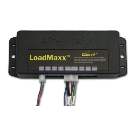
OVERVIEW Specifications Display Diameter 2.44 inches, Height 3.10 inches Weight: 3.6 oz. Operating Temperature range 0° to 50°C (32° to 122°F) Input voltage: supplied by LoadMaxx ComLink Tractor ComLink (5901) Length 2.84 inches, Width 5.2 inches, Height 1.12inches Weight: 4.7 oz. Operating Temperature range –40°... - Page 9 It is important to calibrate the scale system with the tractor and trailer brakes released to release suspension binding. Calibrating or observing weight readings with the brakes engaged will result in inaccuracy. Air-Weigh recommends calibration and weighing be performed on a level surface with the vehicle adequately chocked to prevent rolling.
-
Page 10: Installation
INSTALLATION Route Air Line from Suspension (Optional; if Tractor Suspension gauge already exists in dash skip to Installing Air Pressure Sensors) Route a 1/4 inch air line from the airbag suspension to the dash. Use a 1/4 inch brass street-T at the top of a convenient drive axle suspension air bag to access air pressure. -
Page 11: Installing Air Pressure Sensor(S)
Install brass fitting (150-4083-000) into rear of bulkhead fitting. Run air line (380-0050-000) from brass fitting in rear of tractor bulkhead up into dash to within 3‘ of comlink location. Secure with wire-ties. Connect sensor assembly (reference Installing Air Pressure Sensor(s), below) to end of air line in dash. Using sensor cable, connect sensor to appropriate port in comlink (Sensor B, or C if dual leveling valves). -
Page 12: Kit Configuration Sensor Assignment
KIT CONFIGURATION SENSOR ASSIGNMENT Number Sensor Installed Sensor Type ComLink Sensor Cable See Kit Part AP = Air Pressure Sensor on this Suspension DS = Deflection Sensor Number for Model Input Jack HY = Hydraulic Sensor Number LC = Load Cell 5800 Drive Sensor A... - Page 13 KIT CONFIGURATION SENSOR ASSIGNMENT, cont‘d Model Number Sensor Installed Sensor Type ComLink Sensor Cable See Kit Part AP = Air Pressure Sensor on this Suspension DS = Deflection Sensor Number for Model Input Jack HY = Hydraulic Sensor Number 5826 Drive Sensor A DRIV 1 &...
-
Page 14: Cutting Hole In Dash And Mounting Weight Gauge
KIT CONFIGURATION SENSOR ASSIGNMENT, cont‘d Model Number Sensor Installed Sensor Type ComLink Sensor Cable See Kit Part AP = Air Pressure Sensor on this Suspension DS = Deflection Sensor Number for Model Input Jack HY = Hydraulic Sensor Number Drive, Dual Height Control Valves, AP, AP Sensor A &... -
Page 15: Connecting The Comlink Wiring Harness
Connecting the ComLink Wiring Harness The ComLink wiring harness connects the Air-Weigh system to the vehicle‘s power and ground circuits, the ComLink to the display gauge, and the alarm output to a customer-provided warning device. Those wires with connectors can only be connected to devices in one order, because the connectors are all different. -
Page 16: Secure Cables And Air Lines. Re-Assemble The Dash
Use wire ties through the holes in the ComLink‘s mounting ears to secure it to any appropriate wire harness behind the dash. Find a flat location where ComLink can be attached using the 2-sided adhesive tape already in position on the back of the ComLink. -
Page 17: Scale Display Overview
Scale Display Overview With the installation complete, the next step in setting up your Air- Weigh Tractor Scale is to calibrate it. Before starting that process it‘s a good idea to become familiar with the Panel Display on the front of your scale. Below is a definition of what each button is used for. -
Page 18: Preliminary Considerations
weight ratio. You can also calibrate Air-Weigh Trailer Scales in the same manner by using the Tractor Scale keypad. When selecting this calibration method it is imperative to enter empty weights when the vehicle is empty and heavy weights when the vehicle is loaded heavy. - Page 19 Scales also have a PIN lock-out to prevent tampering when the trailer is parked, however any Air-Weigh equipped tractor will still have access to the Trailer Scale‘s calibration function through the in-cab truck scale. See page 27 for PIN information. 5th Wheel Location Details If your truck scale system uses the Air-Weigh "calculated steer weight"...
-
Page 20: Calibrating The Tractor Scale Overview
CALIBRATING THE TRACTOR SCALE OVERVIEW For Manual Calibration the EMPTY and HEAVY axle weights must be entered by the user. When calibrating using this method the EMPTY weights must be entered while the vehicle is empty, and the HEAVY weights must be entered while the vehicle is fully loaded. Failure to calibrate scales when vehicle is actually empty and when it has a true heavy load will result in inaccurate weights. -
Page 21: Empty Weights
CALIBRATING EMPTY WEIGHTS Press <ESC> one or more times until the ―top menu‖ appears, with VIEW WEIGHTS blinking. Press the down arrow <> 2 times until PRINT, SETUP begins blinking. Press <ENTER>. Press the down arrow <> 1 time until SYSTEM SETUP begins blinking. -
Page 22: Calibration By Direct Entry Of Ratio And Offset
CALIBRATION is now blinking. Press <ENTER>. Press the down arrow <> 1 time until MANUAL CALIB begins blinking. Press <ENTER>. Press the down arrow <> 1 time until HEAVY WEIGHT begins blinking. Press <ENTER>. The screen pauses for three seconds with the display, ―ENTER HEAVY WEIGHTS –... -
Page 23: Enter The Ratio And Offset
Press the down arrow <> 2 times until PRINT, SETUP begins blinking. Press <ENTER>. Press the down arrow <> 2 times until DIAGNOSTICS begins blinking. Press <ENTER>. Press the down arrow <> 2 times until COMLINKS begins blinking. Press <ENTER>. Press the down arrow <>... - Page 24 Use the down arrow <> to select the axle whose suspension you wish to calibrate. When it is blinking, press <ENTER>. A “Manufacturer’s PIN” is needed for direct ratio / offset entry. Contact Air-Weigh Support for more information. 10. Using the up/down arrows <> scroll to the proper ratio, obtained as described in the previous section, but without the decimal point.
-
Page 25: Adjust Weights Worksheet
Adjust Weights Worksheet (Ground Scale Weight) ________ (A) (AW Displayed Weight) ________ (B) (Subtract B from A. C is the Adjustment weight) Adjusting Weight _________ (C) (It‘s OK if a negative appears) Adjust Weights Press <ESC> one or more times until the ―top menu‖ appears, with VIEW WEIGHTS blinking. -
Page 26: Operations
OPERATIONS Once calibrated, your Air-Weigh LoadMaxx Tractor Scale is ready to display weights in 20lb (20kg) increments, and be accurate to within 300lbs (140kgs) of a certified ground scale. Continued accuracy is established by following a few simple rules before taking weight readings: Park the tractor and trailer on a level surface. -
Page 27: Creating A Pin
Press the down arrow <> 1 time until SYS CONFIG begins blinking. Press <ENTER>. DISPLY SETUP is now blinking. Press <ENTER>. Press the down arrow <> 1 time until SHOW / HIDE begins blinking. Press <ENTER>. Press the down arrow <> 2 times until SHOW HELP begins blinking. -
Page 28: Alarm Function
The new PIN is now entered into the scale. To later establish a new PIN, go back through these instructions and change the setting. Setting the PIN back to ZERO will reset the scale to its original status of NO PIN needed. -
Page 29: Turning On The Alarm Feature
GVW, NET ALM 1 is now blinking. Press <ENTER> to select one of these, or press the down arrow <> 1 time until TRCTR ALRMS1 begins blinking, or press the down arrow <> 2 times until TRLER ALRMS1 begins blinking. Press <ENTER>. Depending on the previous step, select from GVW ALARM and NET ALARM;... -
Page 30: Languages
NOTE: Remember, to deactivate and reset an active warning or alarm weight, simply press the Enter button <ENTER> once while alarms are active, while weights are being displayed. To turn the alarm function completely off, go back to the TURN ON/OFF portion of the ALARMS menu and change the (Now ON) back to a (Now OFF). - Page 31 Press the down arrow <> 2 times until BACKLIGHT begins blinking. Press <ENTER>. Press the <> buttons to select the desired time period. Press ENTER. This backlight will automatically dim to the ―sleep mode‖ after the selected operation time period. To turn on the backlight, press any button.
-
Page 32: Quick Reference Menu Directory
QUICK REFERENCE MENU DIRECTORY LoadMaxx Scale System CALIBRATION REQUIRED PRINT, SETUP BEFORE USE SETUP only shows if data stream WEIGHTS PRINT MENU if no data stream) ALARMS PRINT REPORT PRINT, SETUP DATE / TIME SETUP REPRT COPIES only shows if data stream SYSTEM SETUP PRINT MENU if no data stream... -
Page 33: Menu Operations And Definitions
MENU OPERATIONS AND DEFINITIONS Press the <ESC> button one or more times to reach the Top Menu. Use the <> and <> buttons to scroll to new selections. Refer to the Quick Reference Menu Directory above for the entire menu structure. Weight Display Overview Use the up/down arrows <>... -
Page 34: Lbs / Kgs
http://www.air-weighscales.com/support/manuals.cfm, for details. In addition, select REPRT COPIES to set the number of report copies. SYSTEM SETUP MENU CALIBRATION – See the CALIBRATION MENU section, above. SYS CONFIG – See the SYS CONFIG MENU subsection, below. SET PIN # – See the CREATING A PIN section, above. SYS CONFIG MENU DISPLY SETUP –... -
Page 35: Trl Frt/Rear
TRL FRT/REAR – For all models listed under MORE OPTIONS immediately above, allows the Weights Display to show two trailers as TRL A and TRL B or TRAILER, TRL F, and TRL R (―DOLLY‖). If DOLLY is selected, TRAILER gives the sum of TRL F (front) and TRL R (rear). FIRST DISPLY –... -
Page 36: Show / Hide Menu
SHOW / HIDE MENU SHOW GVW – Causes the GVW / Net screen to be visible or not, depending on whether there is an Air-Weigh Trailer Scale present. SHOW GVW lets the GVW / Net screen be visible even without a trailer. HIDE GVW requires an Air-Weigh Trailer Scale to be present in order to access the GVW / Net screen. -
Page 37: A/D Readings
A/D READINGS – Shows the sensor reading for each axle group in A/D (electronic) values, PSI and Bars. Values are shown on a different display for each axle group. Use the up/down arrows <> to scroll between the axle groups. A reading of 409 indicates a sensor fault, sensor cable unplugged, no sensor, etc. -
Page 38: Troubleshooting Chart
Press <ESC> one or more times until the ―top menu‖ appears, with VIEW WEIGHTS blinking. Press the down arrow <> 2 times until PRINT, SETUP begins blinking. Press <ENTER>. Press the down arrow <> 2 times until DIAGNOSTICS begins blinking. Press <ENTER>. With the word STATUS flashing, press <ENTER>... -
Page 39: Incorrect Weight Readings
INCORRECT WEIGHT READINGS If weights are always off by the same amount, see the subsection ADJUST WEIGHTS in the CALIBRATION section, above. If weights are otherwise incorrect, including 0 (zero) or unstable, ensure that the sensor is connected to the Truck ComLink or Trailer Scale correctly. - Page 40 Ride Height Symptoms: Scale readout accuracy varies from certified weight, by varying amounts. Solution: Proper ride height is the most important factor in ensuring accuracy. Ride height is normally defined as the vertical distance from the center of the axle to the bottom of the frame rail. This varies by vehicle and suspension make, so check the proper manual.
-
Page 41: Maintenance
MAINTENANCE Scale Display: The Air-Weigh electronic scale display should be maintenance-free under normal operation. Keep the scale in a protected environment and treat as any electronic component. Gently use a clean, soft cloth, slightly damp with water, to wipe away dust from the display. ComLink: The Air-Weigh ComLink should be maintenance-free under normal operation. -
Page 42: J1939 Connection And Communications
J1939 Connections and Communications Use Air-Weigh cable 014-0300-038 (Cable, AW5901, CAN/J1939, flying lead, 3‘) to connect the LoadMaxx to the vehicle J1939 bus. Refer to Product Application Note LoadMaxx J1939 Message Protocol Interface Specification, P/N 901-0095-000, for more information on this subject. Obtaining good tractor/trailer scale communications: To help ensure good tractor scale / trailer scale communications, follow a simple rule in the installation of the LoadMaxx Tractor Scale ComLink. - Page 43 The second measurement: Measure ohms 5802 LoadMaxx Battery Measure the resistance between the cable at the battery positive (+) terminal on the one hand, and the common connection point between the tractor scale and trailer scale power wires on the other. Measurements should be made using an ohmmeter or multi-meter.
-
Page 44: Index Of Application Notes
Index of Application Notes The following Application Notes are available from Air-Weigh Customer Support for additional information on these subjects: 901-0069-000 - Dropping and hooking a 5802 Trailer Scale on a Trailer-Direct system 901-0070-000 - Dropping and hooking a 5802 Trailer Scale on a Two Trailer Direct system 901-0071-000 - Collecting and Entering Calibration 901-0072-000 - 5802 Trailer Scale, Load Distribution and Spread Tandem Axle Air... -
Page 45: Notes And Installation Data
Notes... - Page 46 Installation data See Diagnostics Menu sections, pages 36 – 37, to find the following. Scale Display serial number DIAGNOSTICS / SYSTM STATUS /▼ _________________________ Scale Display software version DIAGNOSTICS / SYSTM STATUS /▼ _________________________ LoadMaxx model number DIAGNOSTICS / COMLINKS / ID _________________________ LoadMaxx serial number DIAGNOSTICS / COMLINKS / ID...
- Page 47 Drive axle calibration ratio DIAG / COMLINKS / CAL /▼▼▼ ▼▼ _________________________ Drive axle calibration offset DIAG / COMLINKS / CAL /▼▼▼ ▼▼ _________________________ Steer axle warning 1 weight DIAGNOSTICS / ALARMS / WEIGHTS _________________________ Steer axle alarm 1 weight DIAGNOSTICS / ALARMS / WEIGHTS _________________________ Drive axle warning 1 weight...
- Page 48 1730 Willow Creek Circle • Eugene, Oregon 97402-9152 USA P.O.Box 24308 • Eugene, Oregon 97402-0437 USA Telephone (541) 343-7884 • Order Desk (888) 459-3444 Customer Support (888) 459-3247 • FAX (541) 431-3121 Hours of Operation: Mon-Fri, 7am – 5pm, Pacific Time www.Air-Weigh.com...
Need help?
Do you have a question about the LoadMaxx ComLink AW5901 and is the answer not in the manual?
Questions and answers