
Related Manuals for Air Weigh QuickLoad


Summary of Contents for Air Weigh QuickLoad
- Page 1 QuickLoad Installation Guide Trucks and Tractors with Air Pressure Drive Air-Weigh Customer Support: 888-459-3247 PN 901-0123-000 R6...
-
Page 2: Table Of Contents
Mounting the QuickLoad Display ......12 Connecting the QuickLoad Wiring Harness ....13 Connecting the QuickLoad to Power ......13 Connecting the QuickLoad to Sensors and Alarms ... 14 Secure Cables and Reassemble the Dash ....14 QuickLoad Connection Diagrams ........ 15 INSTALLING AIR SUSPENSION SENSOR(S) ...... - Page 3 Setting the QuickLoad’s Sensor Configuration ..... 31 Front Panel Buttons..........31 Entering the Sensor Configuration ......32 FOR FURTHER INFORMATION ..........33 LIMITED WARRANTY ..............34...
-
Page 4: Scale Overview
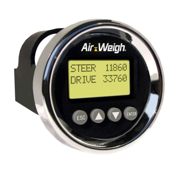
QuickLoad Scale™ for trucks and tractors with ® AP (Air Pressure) drive suspension includes a dashboard- mounted a QuickLoad display, power harness, sensor cable(s), and sensor(s) with mounting hardware. This Installation Guide (p/n: 901-0123-000) gives instructions for scale installations on vehicles having air or spring drive suspensions, possibly in combination with air or spring steer suspensions. -
Page 5: Quickload Tractor Scale Overview
The QuickLoad scale can display up to four axle groups on one tractor/trailer combination. Once the QuickLoad is calibrated for weight, it is not necessary to recalibrate unless the suspension characteristics change. - Page 6 Figure 1. Air Pressure Drive Sensor Hookup Figure 2. Deflection Sensor Drive Sensor Hookup Legend:...
-
Page 7: Installation Overview For Quickload Scale System
Table 7, page 22. A. Overview for Electronic Components Installation Cut hole in dash for display; mount QuickLoad to dash. – OR – Mount QuickLoad in pod on top of dash, using the optional pod mounting kit, P/N: 1225. -
Page 8: Overview For Deflection Sensor(S) Installation
For scales where the steer axle weight is intentionally not displayed (configurations 5803, 5809, 5810, 5816, 5840, 5844, 5850, 5854), no steer axle sensor is needed. For scales with a steer axle with air suspension (configurations 5805, 5806, 5815, 5821, 5826, 5827, 5838, 5842, 5847, 5852, 5856), route air line(s) from steer axle suspension to sensor(s) installed under dash. -
Page 9: Quickload Parts Per Vehicle Type
II. QUICKLOAD PARTS PER VEHICLE TYPE The most popular QuickLoad parts are shown in Table 2, below. 6 for a comprehensive listing of all QuickLoad parts. Table The Air Line and Disconnect kits in Table 2 are optional. They are needed only if the vehicle does not already have those air lines and disconnects, bringing air pressure from the air suspension to behind the dash, already in place. - Page 10 QuickLoad parts per vehicle type, for the most popular software configurations, are shown in Table 3, following. See Table 7 for a comprehensive listing of QuickLoad parts for all vehicle types. All configurations require P/N 1350, QuickLoad Display Kit, which is not otherwise shown in the following table.
-
Page 11: Tools Required (Customer Supplied)
Deflection Sensor Field Test Set The Deflection Sensor Install Field Test Set, p/n 1000, can measure raw deflection sensor readings without the sensor’s connection to the QuickLoad Scale. For installation of the steer axle deflection sensor, refer to p/n 901-0059-000, Steer Axle Deflection Sensor Kit Installation Guide, which is included in kits 1390 and 1391. -
Page 12: Installing The Quickload Scale
000, Steer Axle Deflection Sensor Kit Installation Guide, which is included in kit 1392. INSTALLING THE QUICKLOAD SCALE The installation of an Air-Weigh QuickLoad Scale on a vehicle includes mounting two major classes of components: Electronics components: QuickLoad display and power interface cable ... -
Page 13: Connecting The Quickload Wiring Harness
Figure 3. Installing the Display 2. Connecting the QuickLoad Wiring Harness A. Connecting the QuickLoad to Power The QuickLoad power wiring harness, p/n 012-0600-008, connects the QuickLoad scale to the vehicle’s power and ground circuits. Consult Table 4. . Wiring Harness Hookup Table 4... -
Page 14: Connecting The Quickload To Sensors And Alarms
B. Connecting the QuickLoad to Sensors and Alarms 1. Connect the 4-pin sensor cable(s) to the QuickLoad Sensor Inputs A, B, or C/D, as indicated in the Sensor Connection figures, pages 15-17. 2. To connect an external alarm using the QuickLoad Alarm Kit (p/n 1380), consult the QuickLoad Alarm Kit Manual, included in the Alarm Kit. -
Page 15: Quickload Connection Diagrams
Assignment, for the sensor configuration required for your installation. The following figures give a view of the connectors on the back face of the QuickLoad Scale. They show where the ports for the different configurations mentioned in Table 7 are located. - Page 16 PWR – Power A – Port for connection sensor connection (Optional: 1 alarm connection) B – Port for sensor connection (Optional: alarm connection) Figure 6. Connections for a two sensor system PWR – Power A – Port for connection sensor connection (Optional: 1 alarm...
- Page 17 A – Port for PWR – Power sensor connection connection (Optional: 1 alarm connection) C/D – Port for dual sensor connection Figure 8. Connections for configurations 5821 and 5828 PWR – Power A – Port for connection sensor connection (Optional: 1 alarm connection) C/D –...
- Page 18 Air-Weigh Scale. Enter empty weights only when the vehicle is empty! Enter loaded weights only when the vehicle is loaded! See QuickLoad Calibration and Operations Manual, p/n 901-0124-000, for complete instructions.
-
Page 19: Installing Air Suspension Sensor(S)
V. INSTALLING AIR SUSPENSION SENSOR(S) Air Line Installation for each leveling valve A. Route Air Line from Air Suspension Follow the same instructions for air line and sensor installation for both drive and steer air suspensions. The parts in this section’s instructions are listed in Table 5. -
Page 20: Routing Air Line For Dedicated Tractor / Trailer Scale
air pressure. If you choose to connect in the middle of an existing air line between two air bags, thoroughly remove any paint on the air line and wipe clean before cutting the air line. 3. Route the air line along with other air lines and cables into the dash. - Page 21 150-4091-000 FITTING, BRASS, QUICK COUPLER, MALE 150-4092-000 FITTING, BRASS, ADAPTER PLUG,FEMALE 152-0001-000 BULKHEAD FITTING, 1/4" NPT 100' X ¼” SAE J844 DOT TUBING 380-0050-000 AIR HOSE, COILED, 1/4" NPT X 2, 25’ 380-0053-000 901-0052-000 INSERT, AW5800, TRAILER-DIRECT BOM for Two-Trailer-Direct Disconnect Kit, p/n 010-0029-002 145-4552-001 NYLON TIE, 7", T-50, NYLON, BLK 150-4081-000...
- Page 22 5. Run air line (p/n: 380-0050-000) to front of trailer. Secure with cable ties. 6. Drill hole for trailer bulkhead fitting at a point near where existing airlines attach to trailer. 7. Install bulkhead fitting (p/n: 152-0001-000). 8. Cut air line to length and connect to rear side of bulkhead fitting.
-
Page 23: Installing Sensor(S)
QuickLoad mounting location. Secure with wire ties. 15. Connect open end of air line, near QuickLoad, to push-on fitting on end of Air Pressure Sensor. 16. Connect electrical cable from opposite end of air pressure sensor to appropriate port on QuickLoad. - Page 24 The Air-Weigh kit includes fittings for terminating air lines of either of two diameters, ¼-inch and 5/32-inch. The customer will need to purchase additional fittings to insert a T-fitting into an existing air line. Air-Weigh only supplies the connectors needed for a terminated connection. 1.
-
Page 25: Installing Scales With A Steer Axle Deflection Sensor
B. Installing Scales with a Steer Axle Deflection Sensor When installing kits with configurations 5807, 5808, 5843, 5846, 5853, 5857 or 5878, which include steer axle deflection sensors, refer to p/n 901-0059-000, Steer Axle Deflection Sensor Kit Installation Guide, for installation instructions. For installation of the Hendrickson Walking Beam drive axle deflection sensor, refer to p/n 901-0092- 000, Steer Axle Deflection Sensor Kit Installation... -
Page 26: Parts And Sensor Configuration Tables
C. Parts and Sensor Configuration Tables All configurations require P/N 1350, QuickLoad Display Kit, which is not otherwise shown in the following table. Table 6. QuickLoad Parts for Each Vehicle Configuration Vehicle Drive Steer Trailer Parts Software Description Suspension Suspension... - Page 27 Vehicle Drive Steer Trailer Parts Software Description Suspension Suspension Needed Config 3 ea. 1360 Truck with lift Single HCV Single HCV Not Applicable 5838 axle air sensor 2 ea. 1360 Truck with two lift axle air Def Sensor Def Sensor Not Applicable 1 ea.
- Page 28 Table 7. Kit Configuration Sensor Assignment Sensor Type Number Sensor Installed QuickLoad AP = Air Pressure Sensor Sensor See Kit Part on this Suspension Cable Input Jack Number for DS = Deflection Sensor HCV = Height Control Valve Model Number...
- Page 29 Sensor Type Number Sensor Installed QuickLoad AP = Air Pressure Sensor Sensor See Kit Part on this Suspension Cable Input Jack Number for DS = Deflection Sensor HCV = Height Control Valve Model Number LC = Load Cell Drive Sensor A 5828 <not used>...
- Page 30 Sensor Type Number Sensor Installed QuickLoad AP = Air Pressure Sensor Sensor See Kit Part on this Suspension Cable Input Jack Number for DS = Deflection Sensor HCV = Height Control Valve Model Number LC = Load Cell Drive Sensor A...
-
Page 31: Setting The Quickload's Sensor Configuration
A. Front Panel Buttons 1. When the QuickLoad Display backlight is off, the first button push turns on the backlight, with no other effect. 2. Depressing the ESC key (with the backlight lit) changes the Weights Display to the Main Menu, depicted above. -
Page 32: Entering The Sensor Configuration
B. Entering the Sensor Configuration 1. Depress <ESC> one or more times until the Main Menu appears, with VIEW WEIGHTS blinking. 2. Select SETUP,DIAG leading to next menu. 3. Select SYSTEM SETUP, leading to next menu. 4. Select SYS CONFIG, leading to next menu. 5. -
Page 33: For Further Information
901-0052-000 – Insert, AW5800, Trailer-Direct 901-0065-000 – Insert, AW5800, Two-Trailers-Direct 901-0100-000 – Insert, QuickLoad, Install Guide Included in the QuickLoad Alarm Kit (p/n 1380): 901-0094-000 – QuickLoad Alarm Kit: Installation and Programming Available from Air-Weigh Support: 901-0117-000 – Application Note, Calibrating The Lift Axle... -
Page 34: Limited Warranty
Limited Warranty For product failures due to material or manufacturing defects, Air-Weigh will replace or repair all components for up to 3 years from shipment date to the end-user Air-Weigh customer. These three-year components include: Displays, ComLinks, Sensors, Power Cables, Sensor Assemblies, Sensor Harnesses, and all other associated external components. - Page 35 Procedure For Warranty Claims ALL customers should first contact Air-Weigh Customer Support Department at (888) 459-3247 for questions regarding the use, operation, repair or return of any Air-Weigh product. In the event Air-Weigh requests to examine the product prior to disposition OR for repair or replacement, Air-Weigh requires a Return Material Authorization (RMA) number be issued before the item is returned.
- Page 36 1730 Willow Creek Circle • Eugene, OR 97402-9152 USA P.O. Box 24308 • Eugene, OR 97402-0437 USA Telephone (541) 343-7884 • Order Desk (888) 459-3444 Customer Support (888) 459-3247 • Fax (541) 431-3121 www.Air-Weigh.com...
Need help?
Do you have a question about the QuickLoad and is the answer not in the manual?
Questions and answers