Table of Contents

Related Manuals for Aaeon HSB-CV1P


Summary of Contents for Aaeon HSB-CV1P
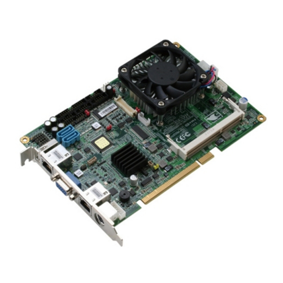
- Page 1 H a l f - s i z e S B C H S B - C V 1 P HSB-CV1P ® Intel Atom D2550/N2600 Processor 10/100/1000Base-TX Ethernet 2 SATA 3.0Gb/s PCI Interface Expansion 8 USB2.0, 4 COM 1 VGA, 1 LVDS HSB-CV1P Manual Rev. A 2 July 2013...
- Page 2 AAEON assumes no liabilities resulting from errors or omissions in this document, or from the use of the information contained herein. AAEON reserves the right to make changes in the product design without notice to its users.
- Page 3 H a l f - s i z e S B C H S B - C V 1 P Acknowledgments All other products’ name or trademarks are properties of their respective owners. AMI is a trademark of American Megatrends Inc. ®...
- Page 4 Packing List Before you begin installing your card, please make sure that the following materials have been shipped: ® 1 HSB-CV1P CPU Card with Active Cooler (Intel ® Atom™ D2550 version) or Passive Heatsink (Intel Atom™ N2600 version) ...
-
Page 5: Table Of Contents
H a l f - s i z e S B C H S B - C V 1 P Contents Chapter 1 General Information 1.1 Introduction..............1-2 1.2 Features ..............1-3 1.3 Specifications ............1-4 Chapter 2 Quick Installation Guide 2.1 Safety Precautions ............ - Page 6 H a l f - s i z e S B C H S B - C V 1 P 2.18 RJ-45 Ethernet (CN6)..........2-11 2.19 RJ-45 Ethernet (CN7)..........2-11 2.20 External +5VSB Input Connector (CN8) ....2-11 2.21 HD Audio Codec with Realtek ALC888 (Optional) Connector (CN9) .............
- Page 7 H a l f - s i z e S B C H S B - C V 1 P 2.42 DDR3 SODIMM Slot (DIMM1) ........ 2-21 Chapter 3 AMI BIOS Setup 3.1 System Test and Initialization........3-2 3.2 AMI BIOS Setup ............3-3 Chapter 4 Driver Installation 4.1 Installation ..............
-
Page 8: Chapter 1 General Information
H a l f - s i z e S B C H S B - C V 1 P Chapter General Information 1- 1 Chapter 1 General Information... -
Page 9: Introduction
(three RS-232, one RS-232/422/485) and 8-bit digital I/O are configured on the HSB-CV1P as well. Full functions make HSB-CV1P user friendly. This brand new slot CPU board is developed to suit the requirements of Industrial/Factory Automation, Transportation, banking machine, ITS, HMI and workstation applications. -
Page 10: Features
H a l f - s i z e S B C H S B - C V 1 P 1.2 Features ® Onboard Intel Atom™ D2550/ N2600 Processor ® Intel NM10 DDR3 800 / 1066 SODIMM x 1, max. 4GB (D2550), 2GB (N2600) ®... -
Page 11: Specifications
H a l f - s i z e S B C H S B - C V 1 P 1.3 Specifications System ® Processor Intel Atom™ D2550/ N2600 processor, (1.86 GHz for D2550, 1.6 GHz for N2600) System Memory 204-pin DDR3 SODIMM x 1, Max. - Page 12 H a l f - s i z e S B C H S B - C V 1 P Power Requirement +12V, ATX Battery Lithium battery Board Size 7.3”(L) x 4.8”(W) (185mm x 122mm) Gross Weight 0.75 lb (0.35 Kg) ...
- Page 13 H a l f - s i z e S B C H S B - C V 1 P Storage SATA 3.0Gb/s x 2 Serial Port COM x 4 (box header) COM2 : RS-232/422/485 (Box header 2.0mm) COM1, COM3, COM4 :RS-232 (Box header 2.0mm) ...
-
Page 14: Chapter 2 Quick Installation Guide
H a l f - S i z e S B C H S B - C V 1 P Chapter Quick Installation Guide Chapter 2 Quick Installation Guide... -
Page 15: Safety Precautions
H a l f - S i z e S B C H S B - C V 1 P 2.1 Safety Precautions Always completely disconnect the power cord from your board whenever you are working on it. Do not make connections while the power is on, because a sudden rush of power can damage sensitive electronic components. -
Page 16: Location Of Connectors And Jumpers
H a l f - S i z e S B C H S B - C V 1 P 2.2 Location of Connectors and Jumpers Component Side Component Side Solder side Chapter 2 Quick Installation Guide... -
Page 17: Mechanical Drawing
H a l f - S i z e S B C H S B - C V 1 P 2.3 Mechanical Drawing Component Side Component Side Solder side Chapter 2 Quick Installation Guide... -
Page 18: List Of Jumpers
H a l f - S i z e S B C H S B - C V 1 P 2.4 List of Jumpers The board has a number of jumpers that allow you to configure your system to suit your application. The table below shows the function of each of the board's jumpers: Label Function... - Page 19 H a l f - S i z e S B C H S B - C V 1 P Front Panel Connector 2 VGA1 Analog CRT Display Connector USB1 USB Port #0 and #1 Connector USB2 USB Port #2 and #3 Connector USB3 USB Port #4 and #5 Connector USB4...
-
Page 20: Setting Jumpers
H a l f - S i z e S B C H S B - C V 1 P 2.6 Setting Jumpers You configure your card to match the needs of your application by setting jumpers. A jumper is the simplest kind of electric switch. It consists of two metal pins and a small metal clip (often protected by a plastic cover) that slides over the pins to connect them. -
Page 21: Clear Cmos (Jp1)
H a l f - S i z e S B C H S B - C V 1 P 2.7 Clear CMOS (JP1) Function Normal (Default) Clear CMOS 2.8 LVDS Operating Voltage Selection (JP2) Function +3.3V (Default) 2.9 LVDS Inverter/ Backlight Voltage Selection (JP3) Function +12V +5V (Default) -
Page 22: Com2 Ri/+5V/+12V Selection (Jp6)
H a l f - S i z e S B C H S B - C V 1 P 2.12 COM2 RI/+5V/+12V Selection (JP6) Function +12V RI (Default) 2.13 LVDS Inverter/ Backlight Connector (CN1) Signal 12V / 5V VCON INV_EN 2.14 LVDS Connector(CN2) Signal... -
Page 23: Keyboard Connector (Cn3)
H a l f - S i z e S B C H S B - C V 1 P LVDS1_DATA3# LVDS1_DATA3 LVDS_DDC_DATA LVDS_DDC_CLK LVDS2_DATA0# LVDS2_DATA0 LVDS2_DATA1# LVDS2_DATA1 LVDS2_DATA2# LVDS2_DATA2 LVDS2_DATA3# LVDS2_DATA3 LVDSVCC LVDS2_CLK# LVDS2_CLK 2.15 Keyboard Connector (CN3) Signal KB_CLK KB_DATA N.C. -
Page 24: Digital I/O Connector (Cn5)
H a l f - S i z e S B C H S B - C V 1 P 2.17 Digital I/O Connector (CN5) Signal Signal OUT0 OUT1 OUT2 OUT3 +3.3V 2.18 RJ-45 Ethernet (CN6) Standard specification 2.19 RJ-45 Ethernet (CN7) Standard specification 2.20 External +5VSB Input Connector (CN8) Signal... -
Page 25: Hd Audio Codec With Realtek Alc888 (Optional)
H a l f - S i z e S B C H S B - C V 1 P 2.21 HD Audio Codec with Realtek ALC888 (Optional) Connector (CN9) Signal Signal SYNC SDIN SDOUT BCLK +3.3V 2.22 USB Port #7 Connector (CN10) Signal +5VSB USB7N... -
Page 26: Front Panel Connector 1 (Fp1)
H a l f - S i z e S B C H S B - C V 1 P 2.23 Front Panel Connector 1 (FP1) Signal Signal Power On Button (+) Reset Switch (+) Power On Button (-) Reset Switch (-) HDD LED (+) Power LED (+) HDD LED (-) -
Page 27: Usb Port #0 And #1 Connector (Usb1)
H a l f - S i z e S B C H S B - C V 1 P 2.26 USB Port #0 and #1 Connector (USB1) Signal Signal +5VSB USB0N USB0P USB1P USB1N +5V_USB 2.27 USB Port #2 and #3 Connector (USB2) Signal Signal +5VSB... -
Page 28: Usb Port #4 And #5 Connector (Usb3)
H a l f - S i z e S B C H S B - C V 1 P 2.28 USB Port #4 and #5 Connector (USB3) Signal Signal +5VSB USB4N USB4P USB5P USB5N +5V_USB 2.29 USB Port #6 Connector (USB4) 2 3 4 Signal +5VSB... -
Page 29: Rs-232/422/485 Serial Port2 Connector (Com2)
H a l f - S i z e S B C H S B - C V 1 P Signal Signal DCD1 RXD1 TXD1 DTR1 DSR1 RTS1 CTS1 2.31 RS-232/422/485 Serial port2 Connector (COM2) RS-232: Signal Signal DCD2 RXD2 TXD2 DTR2 DSR2... -
Page 30: Serial Port3 Connector (Com3)
H a l f - S i z e S B C H S B - C V 1 P TXD+ RXD- NC/+5V/+12V 2.32 RS-232 Serial port3 Connector (COM3) Signal Signal DCD3 RXD3 TXD3 DTR3 DSR3 RTS3 CTS3 2.33 RS-232 Serial port4 Connector (COM4) Signal Signal DCD4... -
Page 31: Parallel Port Connector (Lpt1)
H a l f - S i z e S B C H S B - C V 1 P Signal IRRX IRTX 2.35 Parallel Port Connector (LPT1) Signal Signal STB# AFD# DATA0 ERR# DATA1 INIT# DATA2 SLIN# DATA3 DATA4 DATA5 DATA6 DATA7... -
Page 32: Sata Port2 Connector (Sata1)
H a l f - S i z e S B C H S B - C V 1 P 2.36 SATA Port2 Connector (SATA1) Pin 1 Pin 7 Signal SATA_TX+ SATA_TX- SATA_RX- SATA_RX+ 2.37 SATA Port1 Connector (SATA2) Pin 1 Pin 7 Signal SATA_TX+... -
Page 33: Bios Debug Port (Spi1)
H a l f - S i z e S B C H S B - C V 1 P 2.38 BIOS Debug Port (SPI1) Signal Signal +3.3V SPI_CE# SPI_CLK SPI_SO SPI_SI SPI_HOLD# 2.39 3-Pin CPU Fan Connector (4-Pin Optional) (FAN1) Signal +12V FAN_TAC... -
Page 34: 4-Pin Atx Power Connector (Atx1)
H a l f - S i z e S B C H S B - C V 1 P +12V FAN_TAC FAN_CTL 2.41 4-Pin ATX Power Connector (ATX1) Signal Signal +12V +12V 2.42 DDR3 SODIMM Slot (DIMM1) Standard specification 2-21 Chapter 2 Quick Installation Guide... - Page 35 H a l f - S i z e S B C H S B - C V 1 P Below Table for China RoHS Requirements 产品中有毒有害物质或元素名称及含量 AAEON Main Board/ Daughter Board/ Backplane 有毒有害物质或元素 部件名称 铅 汞 镉 六价铬 多溴联苯...
- Page 36 H a l f - s i z e S B C H S B - C V 1 P Chapter BIOS Setup Chapter 3 AMI BIOS Setup 3-1...
- Page 37 4. The CMOS memory has lost power and the configuration information has been erased. The HSB-CV1P CMOS memory has an integral lithium battery backup for data retention. However, you will need to replace the complete unit when it finally runs down.
- Page 38 H a l f - s i z e S B C H S B - C V 1 P 3.2 AMI BIOS Setup AMI BIOS ROM has a built-in Setup program that allows users to modify the basic system configuration. This type of information is stored in battery-backed CMOS RAM and BIOS NVRAM so that it retains the Setup information when the power is turned off.
- Page 39 H a l f - s i z e S B C H S B - C V 1 P Setup Menu Setup submenu: Main Chapter 3 AMI BIOS Setup 3-4...
- Page 40 H a l f - s i z e S B C H S B - C V 1 P Setup submenu: Advanced Chapter 3 AMI BIOS Setup 3-5...
- Page 41 H a l f - s i z e S B C H S B - C V 1 P ACPI Settings Options Summary : ACPI Sleep State S3 Only (Suspend to RAM) Default Suspend Disabled Select ACPI sleep state the system will enter when the SUSPEND button is pressed. Chapter 3 AMI BIOS Setup 3-6...
- Page 42 H a l f - s i z e S B C H S B - C V 1 P S5 RTC Wake Settings Options Summary : Wake system with Disabled Default Fixed Time Enabled Enable or disable System wake on alarm event. When enabled, System will wake on the hr::min::sec specified.
- Page 43 H a l f - s i z e S B C H S B - C V 1 P CPU Configuration Options Summary : Hyper-Threading Disabled Enabled Default Enabled for Windows XP and Linux (OS optimized for Hyper-Threading Technology) and Disabled for other OS (OS not optimized for Hyper-Threading Technology).
- Page 44 H a l f - s i z e S B C H S B - C V 1 P SATA Configuration (IDE) Options summary : SATA Controller(s) Enabled Default Disabled Enable or disable SATA device. SATA Mode Selection Default AHCI Determines how SATA controller(s) operate.
- Page 45 H a l f - s i z e S B C H S B - C V 1 P SATA Configuration (AHCI) Options summary : SATA Port 0 Disable Enabled Default Enable or Disable SATA Port. SATA Port 0 Hot Plug Disable Enabled Default...
- Page 46 H a l f - s i z e S B C H S B - C V 1 P USB Configuration Options summary : Legacy USB Support Enabled Default Disabled Auto Enable Legacy USB support. Auto option disables legacy support if no USB devices are connected.
- Page 47 H a l f - s i z e S B C H S B - C V 1 P F81866 Super IO Configuration Options Summary : Serial Port 1 Configuration Set Parameters of Serial Port 1 (COMA) Serial Port 2 Configuration Set Parameters of Serial Port 2 (COMB) Serial Port 3 Configuration Set Parameters of Serial Port 3 (COMC) Serial Port 4 Configuration Set Parameters of Serial Port 4 (COMD) IrDA Configuration...
- Page 48 H a l f - s i z e S B C H S B - C V 1 P Serial Port 1 Configuration Options Summary : Serial Port Disabled Enabled Default Enable or Disable Serial Port (COM) Change Settings Auto Default IO=3F8h;...
- Page 49 H a l f - s i z e S B C H S B - C V 1 P Serial Port 2 Configuration Options Summary : Serial Port Disabled Enabled Default Enable or Disable Serial Port (COM) Change Settings Auto Default IO=2F8h;...
- Page 50 H a l f - s i z e S B C H S B - C V 1 P Select an optimal setting for Super IO device. Device Mode RS-232 Default RS-422 RS-485 Change the Serial Port mode. Select <RS-232> or <RS-422> or <RS-485> mode. Chapter 3 AMI BIOS Setup 3-15...
- Page 51 H a l f - s i z e S B C H S B - C V 1 P Serial Port 3 Configuration Options Summary : Serial Port Disabled Enabled Default Enable or Disable Serial Port (COM) Change Settings Auto Default IO=3E8h;...
- Page 52 H a l f - s i z e S B C H S B - C V 1 P Serial Port 4 Configuration Options Summary : Serial Port Disabled Enabled Default Enable or Disable Serial Port (COM) Change Settings Auto Default IO=2E8h;...
- Page 53 H a l f - s i z e S B C H S B - C V 1 P IrDA Configuration Options Summary : Serial Port Disabled Enabled Default Enable or Disable Serial Port (COM) Change Settings Auto Default IO=2C0h;...
- Page 54 H a l f - s i z e S B C H S B - C V 1 P Device Mode Disable IR1 function Enable IR1 Default function, active pulse 1.6uS Enable IR1 function, active pulse 3/16 bit time Select an optimal setting for Super IO device.
- Page 55 H a l f - s i z e S B C H S B - C V 1 P Parallel Port Configuration Options Summary : Serial Port Disabled Enabled Default Enable or Disable Parallel Port (LPT/LPTE) Change Settings Auto Default IO=378h;...
- Page 56 H a l f - s i z e S B C H S B - C V 1 P IO=378h; IRQ=5 ; DMA=3 IO=378h; IRQ=5,6,7,10,11,12;DMA=1,3 IO=278h; IRQ=5,6,7,10,11,12;DMA=1,3 IO=3BCh; IRQ=5,6,7,10,11,12;DMA=1,3 Select an optimal setting for Super IO device. Change Settings Auto Default IO=378h;...
- Page 57 H a l f - s i z e S B C H S B - C V 1 P F81866 H/W Monitor Chapter 3 AMI BIOS Setup 3-22...
- Page 58 H a l f - s i z e S B C H S B - C V 1 P Smart Fan Mode Configuration Options Summary : Fan 1 Confinguration Set Parameters of Fan 1 Fan 2 Confinguration Set Parameters of Fan 2 Chapter 3 AMI BIOS Setup 3-23...
- Page 59 H a l f - s i z e S B C H S B - C V 1 P CPU Fan Confinguration Options Summary : CPU Smart Fan Control Auto by RPM Default Auto by Duty-Cycle Manual by RPM Manual by Duty-Cycle Smart Fan Mode settting Target Temp.
- Page 60 H a l f - s i z e S B C H S B - C V 1 P Temperature Bound 2 Default 50 Temperature Bound 3 Default 40 Temperature Bound 4 Default 30 Segment 1 Speed (%) Default 100 Segment 2 Speed (%) Default 85 Segment 3 Speed (%)
- Page 61 H a l f - s i z e S B C H S B - C V 1 P SYS Fan Confinguration Options Summary : SYS Smart Fan Control Auto by RPM Auto by Duty-Cycle Default Manual by RPM Manual by Duty-Cycle Smart Fan Mode settting Target Temp.
- Page 62 H a l f - s i z e S B C H S B - C V 1 P Temperature Bound 2 Default 50 Temperature Bound 3 Default 40 Temperature Bound 4 Default 30 Segment 1 Speed (%) Default 100 Segment 2 Speed (%) Default 85 Segment 3 Speed (%)
- Page 63 H a l f - s i z e S B C H S B - C V 1 P Digital IO Options Summary : DIO_P#1 Input Default Output Set Digital IO as Input or Output DIO_P#1 Direction Default Set Digital IO Level as Low or Hi DIO_P#2 Input Default...
- Page 64 H a l f - s i z e S B C H S B - C V 1 P DIO_P#2 Direction Default Set Digital IO Level as Low or Hi DIO_P#3 Input Default Output Set Digital IO as Input or Output DIO_P#3 Direction Default Set Digital IO Level as Low or Hi...
- Page 65 H a l f - s i z e S B C H S B - C V 1 P DIO_P#6 Direction Default Set Digital IO Level as Low or Hi DIO_P#7 Input Output Default Set Digital IO as Input or Output DIO_P#7 Direction Default Set Digital IO Level as Low or Hi...
- Page 66 H a l f - s i z e S B C H S B - C V 1 P Setup submenu: Chipset Chapter 3 AMI BIOS Setup 3-31...
- Page 67 H a l f - s i z e S B C H S B - C V 1 P Host Bridge Chapter 3 AMI BIOS Setup 3-32...
- Page 68 H a l f - s i z e S B C H S B - C V 1 P Intel IGD Configuration Options Summary : IGFX – Boot Type VBIOS Default Default LVDS Select the Video Device which will be activated during POST. This has no effect if external graphics present.
- Page 69 H a l f - s i z e S B C H S B - C V 1 P 1024x600,18bit,60Hz 1024x768,18bit,60Hz 1024x768,24bit,60Hz 1280x768,24bit,60Hz 1366x768,24bit,60Hz Select LCD panel used by Internal Graphics Device by selecting the appropriate setup item. Active LFP No LVDS LVDS Default...
- Page 70 H a l f - s i z e S B C H S B - C V 1 P Select Backlight brightness of LVDS. Backlight Control PWM Inverted PWM Normal Default Back Light Control Setting Fixed Graphics Memory 128MB Size 256MB Default...
- Page 71 H a l f - s i z e S B C H S B - C V 1 P South Bridge Options Summary : Azalia Controller Disabled HD Audio Default Azalia Controller. Select USB Mode By Port By Controller Default Select USB mode to control USB ports.
- Page 72 H a l f - s i z e S B C H S B - C V 1 P 3 USB Ports 4 USB Ports 5 USB Ports 6 USB Ports 7 USB Ports 8 USB Ports Default Enable / Disable USB Function. UHCI #1 (ports 0 and 1) Disabled Enabled...
- Page 73 H a l f - s i z e S B C H S B - C V 1 P Enabled Default Enable or Disable USB 2.0 (EHCI) Support. Chapter 3 AMI BIOS Setup 3-38...
- Page 74 H a l f - s i z e S B C H S B - C V 1 P Setup submenu: Boot Options summary : Bootup NumLock State Select keyboard NumLock State. Quiet Boot Disabled Enabled Default Enables or disables Quiet Boot option. Launch RTL8111E PXE Disabled Default...
- Page 75 H a l f - s i z e S B C H S B - C V 1 P Boot Option Priorities Options Summary : Boot Option #X Your device Your device Sets the system boot order Chapter 3 AMI BIOS Setup 3-40...
- Page 76 H a l f - s i z e S B C H S B - C V 1 P Setup submenu: Security Change User/Supervisor Password You can install a Supervisor password, and if you install a supervisor password, you can then install a user password. A user password does not provide access to many of the features in the Setup utility.
- Page 77 H a l f - s i z e S B C H S B - C V 1 P Setup submenu: Exit Chapter 3 AMI BIOS Setup 3-42...
- Page 78 H a l f - s i z e S B C H S B - C V 1 P Chapter Driver Installation 4 - 1 Chapter 4 Driver Installation...
- Page 79 H a l f - s i z e S B C H S B - C V 1 P The HSB-CV1P comes with a CD-ROM that contains all drivers and utilities that meet your needs. Follow the sequence below to install the drivers: Step 1 –...
- Page 80 H a l f - s i z e S B C H S B - C V 1 P 4.1 Installation: Insert the HSB-CV1P CD-ROM into the CD-ROM Drive. And install the drivers from Step 1 to Step 7 in order. Step 1 – Install Chipset Driver 1.
- Page 81 H a l f - s i z e S B C H S B - C V 1 P Follow the instructions that the window shows The system will help you install the driver automatically 4 - 4 Chapter 4 Driver Installation...
- Page 82 H a l f - s i z e S B C H S B - C V 1 P 4 - 5 Chapter 4 Driver Installation...
- Page 83 H a l f - s i z e S B C H S B - C V 1 P If you want to update driver, please uninstall driver first. Uninstall IEMGD 1. Double click on the IEMGDInstall.exe 2. Follow the instructions that the window shows 3.
- Page 84 H a l f - s i z e S B C H S B - C V 1 P Double click on the .exe file located in each OS folder Follow the instructions that the window shows The system will help you install the driver automatically Step 5 –...
- Page 85 H a l f - s i z e S B C H S B - C V 1 P 2. Change User Account Control Settings to [Never notify] 3. Reboot and Administrator login. 4 - 8 Chapter 4 Driver Installation...
- Page 86 H a l f - s i z e S B C H S B - C V 1 P 4. To run patch.bat with [Run as administrator]. You also can install the serial port driver for Windows 7 by the Installation Procedure 2 below: -Win7 32-bit Copy the Driver CD\Serial Port Driver...
- Page 87 H a l f - s i z e S B C H S B - C V 1 P Step 6 – Install AHCI Driver Please refer to Appendix D AHCI Setting Step 7 – Install Rapid Storage Technology Driver Click on the STEP7 - Rapid Storage Technology folder and select the OS folder your system is Double click on the setup.exe file located in each OS...
- Page 88 H a l f - s i z e S B C H S B - C V 1 P Appendix Programming the Watchdog Timer Appendix A Programming the Watchdog Timer A-1...
- Page 89 H a l f - s i z e S B C H S B - C V 1 P A.1 Programming HSB-CV1P utilizes FINTEK 81866 chipset as its watchdog timer controller. Below are the procedures to complete its configuration and the AAEON initial watchdog timer program is also attached based on which you can develop customized program to fit your application.
- Page 90 H a l f - s i z e S B C H S B - C V 1 P There are three steps to complete the configuration setup: (1) Enter the MB PnP Mode; (2) Modify the data of configuration registers; (3) Exit the MB PnP Mode.
- Page 91 H a l f - s i z e S B C H S B - C V 1 P Watch Dog Timer 1, 2, 3 Control Register (Index=F5h,F6h,FAh Default=00h) Appendix A Programming the Watchdog Timer A-4...
- Page 92 H a l f - s i z e S B C H S B - C V 1 P A.2 F81866 Watchdog Timer Initial Program Main (){ aaeonSuperIOOpen(); aaeonWdtSetCountMode(BOOL bMinute); // Set wdt count mode aaeonWdtSetTimeoutCount(BYTE tTimeout); // Set wdt timer aaeonWdtSetEnable(BOOL bEnable); // Enable wdt aaeonSuperIOClose(); } Void aaeonSuperIOOpen(){ // Config F81866 Entry key aaeonioWritePortByte(F81866_INDEX, 0x87); aaeonioWritePortByte(F81866_INDEX, 0x87); ...
- Page 93 H a l f - s i z e S B C H S B - C V 1 P Void aaeonWdtSetTimeoutCount(BYTE tTimeout){ f81866SetLdn(0x07); f81866WriteByte(F81866_WDT_TIME_REG, tTimeout); } Void aaeonWdtSetEnable(BOOL bEnable){ f81866SetLdn(0x07); if(bEnable){ f81866WriteByte(0x30, 0x01); WDT_BASE_ADDR = (f81866ReadByte(F81866_WDT_BASEADDR_REG_MSB) << 8) ...
- Page 94 H a l f - s i z e S B C H S B - C V 1 P Void aaeonSuperIOClose(){ aaeonioWritePortByte(F81866_INDEX, 0xaa); } Appendix A Programming the Watchdog Timer A-7...
- Page 95 H a l f - s i z e S B C H S B - C V 1 P Appendix I/O Information B - 1 Appendix B I/O Information...
- Page 96 H a l f - s i z e S B C H S B - C V 1 P B.1 I/O Address Map B - 2 Appendix B I/O Information...
- Page 97 H a l f - s i z e S B C H S B - C V 1 P B - 3 Appendix B I/O Information...
- Page 98 H a l f - s i z e S B C H S B - C V 1 P B.2 1 MB Memory Address Map B - 4 Appendix B I/O Information...
- Page 99 H a l f - s i z e S B C H S B - C V 1 P B.3 IRQ Mapping Chart B - 5 Appendix B I/O Information...
- Page 100 H a l f - s i z e S B C H S B - C V 1 P B - 6 Appendix B I/O Information...
- Page 101 H a l f - s i z e S B C H S B - C V 1 P B.4 DMA Channel Assignments B - 7 Appendix B I/O Information...
- Page 102 H a l f - s i z e S B C H S B - C V 1 P Appendix Mating Connector C - 1 Appendix C Mating Connector...
- Page 103 H a l f - s i z e S B C H S B - C V 1 P C.1 List of Mating Connectors and Cables The table notes mating connectors and available cables. Mating Connector Connector Available Cable P/N Function Label Cable...
- Page 104 H a l f - s i z e S B C H S B - C V 1 P Connector RS-232 Serial COM1 Serial Port CATCH 1147-000-10S Port 1701100305 Connector Cable RS-232/4 Serial 22/485 COM2 CATCH 1147-000-10S Port 1701100305 Serial Port Cable Connector...
- Page 105 H a l f - s i z e S B C H S B - C V 1 P ATX1 Power CATCH 1121-700-04S Connector C - 4 Appendix C Mating Connector...
- Page 106 H a l f - s i z e S B C H S B - C V 1 P A ppendix AHCI Setting Appendix D AHCI Setting...
- Page 107 H a l f - s i z e S B C H S B - C V 1 P D.1 Setting AHCI OS installation to setup AHCI Mode. Step 1: Copy the files below from “Driver CD -> STEP6 - AHCI for XP installation\F6 Install Floppy Create for 32 and 64 bit Windows”...
- Page 108 H a l f - s i z e S B C H S B - C V 1 P Step 4: Press “F6” Step 5: Choose “S” Appendix D AHCI Setting...
- Page 109 H a l f - s i z e S B C H S B - C V 1 P Step 6: Choose “Intel(R) NM10 Express Chipset” Step 7: It will show the model number you select and then press “ENTER Step 8: Setup is loading files Appendix D AHCI Setting...
Need help?
Do you have a question about the HSB-CV1P and is the answer not in the manual?
Questions and answers