Table of Contents
Advertisement
Quick Links
Advertisement
Table of Contents

Related Manuals for Toa IR-820SP


Summary of Contents for Toa IR-820SP
- Page 1 OPERATING INSTRUCTIONS INFRARED WIRELESS SPEAKER IR-820SP Thank you for purchasing TOA’s Infrared Wireless Speaker. Please carefully follow the instructions in this manual to ensure long, trouble-free use of your equipment. TOA Canada Corporation...
-
Page 2: Table Of Contents
6.2. Four microphones system………………………………………………………………..7 7. INSTALLATION PRECAUTIONS ..........7.1. Installation Position ....................8 7.2. Distance Between the Infrared Wireless Microphone and IR-820SP ...... 8 7.3. Radio Noise ......................9 7.4. Connection to IR-802T ..................... 9 7.5. Sunlight and Fluorescent Lighting ................9 8. -
Page 3: Important Safety Instructions
1. IMPORTANT SAFETY INSTRUCTIONS • Read these instructions. • Keep these instructions. • Heed all warnings. • Follow all instructions. • Do not use this apparatus near water. • Clean only with dry cloth. • Do not block any ventilation openings. Install in accordance with the manufacture's instructions. •... -
Page 4: Safety Precautions
WARNING the power supply plug from the AC outlet and contact your nearest TOA dealer. Make no further attempt to operate the unit in this condition as this When Installing the Unit may cause fire or electric shock. -
Page 5: General Description
• Consult the dealer or an experienced radio/television technician for help. 3. GENERAL DESCRIPTION The Infrared Wireless Microphone System using this IR-820SP is a PA system designed for use in the school classrooms assuming that their size is about 10 m x 10 m (30 ft x 30 ft). -
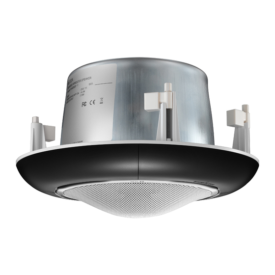
Page 6: Nomenclature And Dimensions
5. NOMENCLATURE AND DIMENSIONS Unit: mm (inches) [Front] [Side] Power indicator 70.5 (2.78) Front grille Infrared filter 205 (8.07) Safety wire [Rear] (accessory) Safety wire hook Choke bracket [Ceiling mounting] ø300 (ø11.81) (Mounting hole) Connector cover Ceiling reinforcement ring Trim ring (accessory) (accessory) [Trim ring (accessory)] [Ceiling reinforcement ring (accessory)]... -
Page 7: System Configuration Example
• Cross type cables cannot be used. • The cable length must not exceed 50 m (54.68 yd). IR-820SP Y 4Q Infrared Wireless Speaker IR-200M Y 4Q Infrared Wireless Microphone IR-802T CU AQ / IR-802T CU 1Q... -
Page 8: Installation Precautions
7.1. Installation Position • Install the IR-820SP in the ceiling in the center of the room whose size should not exceed 10 m x 10 m (30 ft x 30 ft) with ceiling height of 2.5 – 3 m (8.2 – 9.84 ft) so that the Infrared wireless microphone can be used everywhere throughout the room. -
Page 9: Radio Noise
• To prevent the IR-820SP from being directly exposed to sunlight, block the sunlight using curtains or window shades. • When mounting the IR-820SP to a ceiling, keep it at least 2 m (6.56 ft) away from the window. 7.5.2. Install away from fluorescent lighting When installing the IR-820SP, keep it at least 50 cm (1.64 ft) away from the fluorescent lighting. -
Page 10: Mounting Hardware Installation
8. MOUNTING HARDWARE INSTALLATION Before Installing the IR-820SP Determine the most appropriate method for the ceiling structure. Be sure to use an optional HY-TB1 Tile Bar Bridge in combination with the supplied ceiling reinforcement ring. [Installation view on Drop Ceilings] Because the bridge rails are 603 mm (23.74”) in length, be sure to match them to the ceiling tile size during... - Page 11 Step 1. Cut a φ300 mm (11.81”) hole in the ceiling. Use the supplied paper pattern to position and trace the hole. ø300 ± 5 mm (11.81 ± 0.2") Ceiling panel or ceiling tile Step 2. Install the HY-TB1 in the ceiling. Loosen the two reinforcement ring mounting screws in each tie-plate to the point that they do not fall out of their holes.
- Page 12 Step 3. Place the supplied reinforcement ring on the ceiling panel. Mounting hole Fold the reinforcement ring in half* and insert it through the mounting hole in the ceiling panel. * The reinforcement ring is too large to be inserted Ceiling reinforcement ring (accessory) into the mounting hole unless folded.
- Page 13 Step 5. Attach the supplied trim ring to the IR-820SP. Step 6. Attach the supplied safety wire to prevent the IR-820SP from accidentally falling. To attach, tie one end of the safety wire around the speaker’s safety wire hook, and tie its snap ring around solid structure (pipe, building frame, etc.).
-
Page 14: Wiring
• The cable length must not exceed 50 m (54.68 yd). • Be sure to connect the connection cable from the IR-820SP to the "TO IR-820SP" terminal on the IR-802T's rear panel. Never short-circuit the connector nor connect it to the LAN terminal of other device, as this could cause the unit failure. -
Page 15: Speaker Installation
• After detaching the infrared filters, you will find the infrared receiver circuit parts and wirings inside the unit. Never touch them. Step 2. Insert the IR-820SP through the mounting hole till it contacts the ceiling panel. Ceiling Infrared receiver circuit parts... - Page 16 Step 3. Rotate and tighten the 4 mounting tab axis screws on the unit clockwise to their full stop in order to grip the ceiling panel with the mounting tabs. Step 4. Replace the detached 2 infrared filters. Replace each infrared filter by sliding it inward, then secure the filter with 2 screws. Mounting tab Mounting tab axis screw Use an electric screwdriver to tighten.
-
Page 17: Removing The Ir-820Sp For Maintenance
Mounting tab axis screw Screws Notes • When loosening the mounting tab axis screws, support the IR-820SP by hand to prevent it from falling. • Be sure to set the screwdriver’s torque for under Use an electric screwdriver 0.58 N·m (6 kgf·cm.) to detach. -
Page 18: Input Overload Protection Function
12. INPUT OVERLOAD PROTECTION FUNCTION The IR-820SP features an internal input overload protection circuitry. If an extremely high input level is fed to the unit, the protection circuitry automatically cuts off the signal to the speaker element. Note This protection circuitry does not completely protect the unit against extremely high input power levels. -
Page 19: Specifications
15. SPECIFICATIONS IR-820SP Y 4Q Power Source 24 V DC (supplied from IR-802T) Power Consumption 4.4 W (based on UL standard) Rated Output 20 W Frequency Response 100 Hz – 20 kHz (–10 dB) at installation in 1/2 free sound field (Measured by installing the unit in the center of a ceiling.) - Page 20 TOA Canada Corporation 133-07-00125-00...
Need help?
Do you have a question about the IR-820SP and is the answer not in the manual?
Questions and answers