
Related Manuals for Toa IP-A1SC15


Summary of Contents for Toa IP-A1SC15
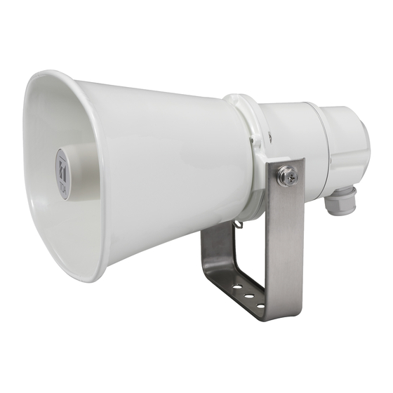
- Page 1 INSTRUCTION MANUAL IP HORN SPEAKER IP-A1SC15 Thank you for purchasing TOA’s IP Horn Speaker. Please carefully follow the instructions in this manual to ensure long, trouble-free use of your equipment.
-
Page 2: Table Of Contents
TABLE OF CONTENTS 1. SAFETY PRECAUTIONS ................3 2. SUMMARY AND FEATURES ..............5 3. ABOUT SECURITY MEASURES ............5 4. DIMENSIONAL DRAWINGS ..............6 5. NOMENCLATURE AND FUNCTIONS ..........7 6. INSTALLATION ....................8 6.1. Attaching the Rear Cover ..................8 6.2. -
Page 3: Safety Precautions
PoE+ on the unit. If the snow lies on the unit, the unit may or PoE switching hub and contact your nearest TOA fall, causing personal injuries. dealer. Make no further attempt to operate the unit in this condition as this may cause fire or electric •... - Page 4 Modifications Any modifications made to this device that are not approved by TOA Corporation may void the authority granted to the user by the FCC to operate this equipment.
-
Page 5: Summary And Features
2. SUMMARY AND FEATURES The IP-A1SC15 IP horn speaker is equipped with a built-in power amplifier and sound source memory. It can be connected to and used over a local network. • Power may be supplied by way of PoE+ or PoE switching hubs. -
Page 6: Dimensional Drawings
4. DIMENSIONAL DRAWINGS [Front] [Side] Unit: mm 276 (10.87") 222 (8.74") (4.17") Mounting bracket 4.5 (0.18") [Mounting bracket bottom surface] Mounting holes [Rear] 36 (1.42") * Figure is a reference value. -
Page 7: Nomenclature And Functions
5. NOMENCLATURE AND FUNCTIONS [Side] [Rear (with rear cover removed)] 1. Mounting bracket 7. LAN port Used to securely mount the unit to a wall or ceiling. Connect to a PoE+ or PoE switching hub using a LAN cable. 2. Rear cover (accessory) This weatherproof cover protects the cable connection Amplifier Rated Output is as follows. -
Page 8: Installation
6. INSTALLATION 6.1. Attaching the Rear Cover [Before attachment] Removable terminal plugs (3 pins) Rear cover (accessory) Screws (3 places) Ring gasket Recess Sealing bush* Hole plug* Sealing clamp* Sealing nut* * Attached to the rear cover when shipped from the factory. Notes •... -
Page 9: Unit Mounting
Step 3. Slide each part over the ends of the LAN cable and control cable Rear cover in the order shown in the figure at right. (accessory) Feed the cable ends through the sealing bush can be more Slot easily done by pressing the cable into the slots in the bush. Sealing bush Step 4. -
Page 10: Connections
• Internal sound source broadcast in progress output (Rear panel) For settings, please refer to the separate setup manual. The latest version of the setup manual is available on the TOA DATA Library (https://www.toa-products.com/international/). From external control device’s control output terminals... -
Page 11: Removable Terminal Plug Connections
7.3. Removable Terminal Plug Connections Please note the following points when making connections to the control input or output terminals using the supplied removable terminal plugs: • Do not tin stripped wire ends with solder. Soldered wire ends will be crushed when the terminal plug screws are tightened, leading to higher contact resistance and potentially resulting in an abnormal rise in the temperature of the connected parts. -
Page 12: Settings
Backup and restoration of settings, initialization, firmware update and restart of hardware. For more information, please refer to the separate setup manual. The latest version of the setup manual is available on the TOA DATA Library (https://www.toa-products.com/ international/). 8.2. System Requirements... -
Page 13: Initialization Of Settings
The Status screen is displayed, enabling a range of settings. Note For details regarding the setting method, please refer to the separate setup manual. The latest version of the setup manual is available on the TOA DATA Library (https://www.toa-products.com/international/). 9. INITIALIZATION OF SETTINGS Follow the procedure below to return all IP horn speaker setting contents to their initial settings: When initialized with the Reset key, the unit’s sound source files are left untouched, and not deleted. -
Page 14: Regarding The Avc/H.264 Patent License
10. CAUTIONS REGARDING THE AVC/H.264 PATENT LICENSE TOA’s IP-A1SC15 IP horn speaker employs MPEG technology (AVC/H.264 Standard) regarding the handling of image information. TOA Corporation has received approval to use this technology from MPEG LA, LLC, the patent management group. -
Page 15: Specifications
11. SPECIFICATIONS Power Source PoE+ (IEEE802.3at Class 4), PoE (IEEE802.3af Class 3) Power Consumption 22 W (at PoE+ powered, rated output) 13 W (at PoE powered, rated output) 5 W (IEC62368-1) Amplifier Rated Output 15 W (at PoE+ powered), 8 W (at PoE powered) Sensitivity 112 dB (1 W, 1 m) (500 Hz to 2.5 kHz, peak level) Maximum... - Page 16 7-2-1, Minatojima-Nakamachi, Chuo-ku, Kobe, Hyogo, 400 Oyster Point Boulevard, Suite 301, Japan South San Francisco, California 94080, Traceability Information for Europe Manufacturer: Authorized representative: TOA Corporation TOA Electronics Europe GmbH 7-2-1, Minatojima-Nakamachi, Chuo-ku, Kobe, Hyogo, Suederstrasse 282, 20537 Hamburg, Japan Germany URL: https://www.toa.jp/ 133-01-00286-00...
Need help?
Do you have a question about the IP-A1SC15 and is the answer not in the manual?
Questions and answers