Table of Contents
Advertisement
Quick Links
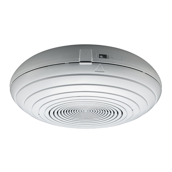
SURFACE-MOUNT SPEAKER
TABLE OF CONTENTS
1. SAFETY PRECAUTIONS .................................................. 2
2. GENERAL DESCRIPTION AND FEATURES ................... 4
3. NOMENCLATURE ............................................................ 4
4. WIRING DIAGRAM ........................................................... 5
5.1. Before Installation ....................................................... 5
5.2. Installation Procedure ................................................. 6
5.3. Removing the Front Case ........................................ 10
6. SPECIFICATIONS ........................................................... 11
Accessories ..................................................................... 11
Thank you for purchasing TOA's Surface-mount Speaker.
Please carefully follow the instructions in this manual to ensure long, trouble-free use of your equipment.
INSTRUCTION MANUAL
PC-2268
Advertisement
Table of Contents

Related Manuals for Toa PC-2268


Summary of Contents for Toa PC-2268
-
Page 1: Table Of Contents
5.2. Installation Procedure ..........6 5.3. Removing the Front Case ........10 6. SPECIFICATIONS ............11 Accessories ..............11 Thank you for purchasing TOA's Surface-mount Speaker. Please carefully follow the instructions in this manual to ensure long, trouble-free use of your equipment. -
Page 2: Safety Precautions
· If water or any metallic object gets into the speaker · If the speaker falls, or the speaker case breaks • To prevent a fire or electric shock, never open nor remove the speaker case. Refer all servicing to your nearest TOA dealer. - Page 3 Indicates a potentially hazardous situation which, if mishandled, could CAUTION result in moderate or minor personal injury, and/or property damage. When Installing the Unit • Never install the speaker in humid or dusty locations, in locations exposed to direct sunlight, or near heaters as doing otherwise may result in fire or electric shock.
-
Page 4: General Description And Features
2. GENERAL DESCRIPTION AND FEATURES The PC-2268 is a surface-mount speaker with rated input of 6 W (100 V line application) designed for ceiling surface or wall surface installations. With the additional use of an electrical box, it can be installed to the location where no wall or ceiling is available for mounting. -
Page 5: Wiring Diagram
4. WIRING DIAGRAM Rear case section Front case section Input terminal Matching transformer HOT (black) 13 kΩ 8Ω 6.7 kΩ Intermediate Intermediate 3.3 kΩ connector connector 1.7 kΩ (black) COM (white) COM (white) Note The input line (black) is connected to 1.7 kΩ tap Bridge at the factory. -
Page 6: Installation Procedure
5.2. Installation Procedure Step 1. Install the rear case to a ceiling or a wall. Route the speaker cables through a cable entry opening (ø 30 mm) in the rear case, then secure the rear case. Following 2 kinds of screws are supplied with the unit. Use these screws properly depending on the intended application. - Page 7 1-2. When installing the rear case to an electrical box; Electrical box Ceiling Rear case Cable entry Reinforcement bracket dimensional diagram opening 5 x 15 5 x 10 5 x 13.5 66.7 83.5 Unit: mm Reinforcement bracket Note Mounting dimension of the reinforcement bracket is Mounting screw 66.7 - 83.5 mm.
- Page 8 Step 2. Connect the speaker cables to the input terminal. Connect both the input line (cable from the amplifier) and bridge line (cable to the next speaker) to the input terminal. Reinforcement bracket Rear case secured to the ceiling or wall Bind the speaker cables to the reinforcement bracket using its idle holes with the cable ties (2 places).
- Page 9 Step 3. Set the input tap. Disconnect the black lead (HOT) connected to the matching transformer, then connect it to the desired input tap. Matching transformer is installed inside the front case. Impedance 1.7 kΩ 3.3 kΩ 6.7 kΩ 13 kΩ 100 V line 1.5 W 0.8 W...
-
Page 10: Removing The Front Case
Step 6. Secure the front case to the rear case. 6-1. Align the positioning mark on the front case ( ) with that on the rear case, then insert the front case to the rear case. Confirm that the cables are not pinched between the cases and that speaker cables do not touch the components inside the speaker. -
Page 11: Specifications
6. SPECIFICATIONS Rated Input 6 W (for 100 V line), 3 W (for 70 V line) Rated Impedance 100 V line: 1.7 kΩ (6 W), 3.3 kΩ (3 W), 6.7 kΩ (1.5 W), 13 kΩ (0.8 W) 70 V line: 1.7 kΩ (3 W), 3.3 kΩ (1.5 W), 6.7 kΩ (0.8 W), 13 kΩ (0.4 W) Sensitivity 90 dB (1 W, 1 m, 330 –... - Page 12 URL: http://www.toa.jp/ 533-06-204-9A...
Need help?
Do you have a question about the PC-2268 and is the answer not in the manual?
Questions and answers