
Related Manuals for LELY DISCOVERY


Summary of Contents for LELY DISCOVERY
- Page 1 D-H002.0607EN LELY INDUSTRIES N.V. DAIRY EQUIPMENT DISCOVERY BARN CLEANER Manual (Dutch original instructions for use) www.lely.com...
- Page 3 Lely, Lely Center, Astronaut, Atlantis, Astri, Astrodata, Calm, Compedes, Cosmix, E-link, Gravitor, Grazeway, Lelywash, Luna, Shuttle, T4C, Viseo and Discovery are registered trademarks of the Lely Group. The right of exclusive use belongs to the companies of the Lely Group.
-
Page 5: List Of Included Amendments
List of included amendments List of included amendments Amendment Date (mm/yy) Chapter(s) Remarks Basic 01/05 Amendments 03/06 Drawings, text and alerts Amendments 07/06 Drawings, text and alerts... - Page 6 List of included amendments...
-
Page 7: Table Of Contents
Safety stickers (if present) ....................xv Introduction........................xvii General view........................xix Registration ........................xxi PACKAGING......................1-1 Charger unit packaging ...................... 1-1 Discovery barn cleaner packaging ..................1-2 INSTALLING THE COMPONENTS ...............2-1 Charger unit ........................2-1 2.1.1 Hoisting point ....................2-2 2.1.2 Placement of the charger unit ................2-2 2.1.3... - Page 8 Hints for programming ......................4-18 4.4.1 General......................4-18 4.4.2 Installation ......................4-19 SERVICE AND MAINTENANCE................5-1 TECHNICAL SPECIFICATIONS ................6-1 TROUBLESHOOTING ..................7-1...
-
Page 9: List Of Illustrations
List of illustrations List of illustrations Figure No. Description Page Discovery barn cleaner (floor-mounted charger unit) ............xix Construction of the charger unit.................... 1-1 Construction of the Discovery barn cleaner................1-2 Construction of the charger unit.................... 2-1 Positioning of the charger unit ....................2-2 Installation dimensions ...................... - Page 10 List of illustrations viii...
-
Page 11: List Of Tables
Alarm list (example) ......................4-15 Alarms and codes ......................... 4-15 Example route........................4-21 Technical specifications of the Discovery barn cleaner and components ......6-1 Technical specifications of the charger unit................6-1 Technical specifications of the TBC 512-1-15 battery charger ..........6-2 Battery .......................... - Page 12 List of tables...
-
Page 13: Safety
WARNING! TAKE CARE! OUR SAFETY IS AT RISK! The safety symbol draws your attention to important safety warnings on your Discovery barn cleaner and in the manual. Wherever you see this symbol, take special care to avoid the risk of (fatal) bodily injury. Observe the instructions on every safety sticker (decal). - Page 14 • Always have the telephone number of the nearest medical centre close at hand. • Contact your nearest Lely service provider if you have any questions. • Review safety-related items frequently (annually) with all those who operate the barn cleaner.
- Page 15 DISCOVERY manual • Contact your nearest Lely service provider if you have any questions. • Hold a regular (annual) safety review with all persons who work with the equipment. INSTALLATION SAFETY • Read and observe the instructions in the manual. By choosing the correct place to install the appliance in your cowshed, and mounting it securely, you will reduce the risk of mechanical errors.
- Page 16 Safety This page intentionally left blank...
-
Page 17: Safety Stickers (If Present)
Safety stickers (if present) Maintenance of safety stickers (decals): The safety decals applied on the Discovery barn cleaner contain important and useful information to ensure that you can continue to use your machine/installation safely. Please follow the instructions provided below to ensure that all decals remain in place and in good condition. - Page 18 Safety stickers (if present) SAFETY INSTRUCTIONS • Read the manual for the barn cleaner unit carefully. Observe all safety measures and instructions. • For more detailed information, please refer to the "Safety" chapter.
-
Page 19: Introduction
This manual is specifically intended for the barn cleaner that has been supplied by the Lely organisation concerned. It is possible that certain options required to adapt this device to specific local conditions will not be covered in this manual. - Page 20 Introduction xviii...
-
Page 21: General View
General view General view Figure 1 Discovery barn cleaner (floor-mounted charger unit) - Page 22 General view...
-
Page 23: Registration
Table 1 Item number and serial number identification plate Type: Ser. no.: The table below shows the item number of the barn cleaner that this manual has been written for. Table 2 Discovery barn cleaner item number Description Item number Discovery barn cleaner... - Page 24 Registration xxii...
-
Page 25: Packaging
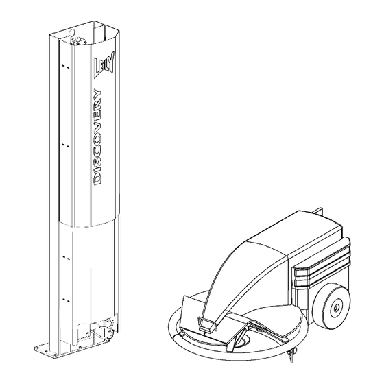
DISCOVERY manual Packaging Charger unit packaging Check that the following components are present in the packaging for the charger unit: Figure 1 1 Construction of the charger unit 1. Floor column (1x) (optional) 7. Battery charger + cabling (packed separately) 8. -
Page 26: Discovery Barn Cleaner Packaging
Packaging Discovery barn cleaner packaging Check that the following components are present in the packaging for the barn cleaner: Figure 1 2 Construction of the Discovery barn cleaner 1. Discovery barn cleaner (complete) 2. E-link manual controller 3. Technical documentation (not shown) -
Page 27: Installing The Components
DISCOVERY manual Installing the components Charger unit Figure 2 1 Construction of the charger unit NOTE • The placement of the charger unit within the cowshed is very important. Place the charger unit somewhere in the cowshed where there is a minimum of cow movements. Avoid drinking troughs and narrow passageways when positioning it. -
Page 28: Hoisting Point
The hoisting eye can be found by opening the black cover. The strip that the hoisting eye is integrated into can be found in front of the battery. This is the lifting eye that can be used for moving the Discovery safely. -
Page 29: Installing The Charger Unit On The Cowshed Floor
DISCOVERY manual 2.1.3 Installing the charger unit on the cowshed floor Fit the electrodes (5, figure 2 1) to the lower support (4) with M8 bolts (4x). Fix the floor column (1) to the shed floor with M10 bolts (8x - not supplied). -
Page 30: Installing The Charger Unit On A Wall
Installing the components 2.1.4 Installing the charger unit on a wall NOTE • For the correct placement within the cowshed, see details as described in figure 2 Fit the electrodes (5, figure 2 1) to the lower support (4) with M8 bolts (4x). Place the support (4), with the electrodes, against the wall. -
Page 31: Installing The Battery Charger
DISCOVERY manual 2.1.5 Installing the battery charger • Before you supply power to the barn cleaner or operate, maintain or adjust the machine, first read the safety instructions carefully and familiarise yourself with all the safety notices. For more information see chapter 'Safety'. - Page 32 Installing the components This page intentionally left blank Chapter 2 - page 6...
-
Page 33: Description Of Components
1) consists of a number of distinct components, namely: Discovery barn cleaner. Charger unit. Electrodes. Battery charger (12V). E-link manual controller. Charger unit E-link Battery charger barn cleaner Electrodes Figure 3 1 Discovery barn cleaning system Chapter 3 - page 1... -
Page 34: Discovery Barn Cleaner
Turns are made and corrected using a built-in electronic gyroscope. The metal ring can follow the wall and can avoid any obstacles such as beams and the legs of the cows and/or calves. The Discovery barn cleaner has the following specific features: • adjustable speed Manure Bolted connection •... -
Page 35: Charger Unit
DISCOVERY manual Charger unit Once pre-programmed, the barn cleaner recharges itself at the charger unit (figure 3 The charger unit can be fitted in the cowshed in two ways: • wall-mounted • floor-mounted A programmed route lets the barn cleaner get back to the charger unit. -
Page 36: E-Link Manual Controller
Description of components E-link manual controller You can use the E-link manual control (figure 3 6) to operate and programme the barn cleaner. The E-link manual controller consists of an LCD display with 9 function buttons. The following buttons are used for operating the barn cleaner: (1) - Next screen/ENTER This button is used to open the selected menu and call up the... -
Page 37: Printed Circuit Board (Multiboard Ads3800B)
DISCOVERY manual Printed circuit board (multiboard ADS3800B) 3.5.1 PCB connectors Table 3.1 Connector 201 - shortcut between pins 1 and 2 Description Colour Voltage (VDC) Not used Shortcut Black Shortcut Black Table 3.2 Connector 202 - Power Description Colour Voltage (VDC) - Page 38 Description of components Table 3.5 Connector 1201 - Gyroscope Description Colour Voltage (DC) Black Green Grey Not used Table 3.6 Connector 1202 - Gyroscope Description Colour Voltage (DC) White Yellow Not used Not used Table 3.7 Connector 1304 - Gyroscope Description Colour Voltage (DC)
- Page 39 DISCOVERY manual Table 3.9 Connector 1306 - Enc 2 Description Colour Voltage (VDC) - GND White Yellow Green + POWER Brown Table 3.10 Connector 1401 - Battery charge current measurement Description Colour Voltage (VDC) + POWER Brown + 0.0 - GND White - 0.0...
- Page 40 Description of components Figure 3 7 PCB connectors (multiboard ADS3800A) Chapter 3 - page 8...
-
Page 41: System Operation
DISCOVERY manual System operation General The route (figure 4 1) that the barn cleaner follows is programmed once only by the farmer using the E-link manual control. Different routes are possible, so that there is the option of cleaning particular paths within the cowshed more intensively at certain times of day. -
Page 42: Programming With The E-Link Manual Control
System operation Programming with the E-link manual control We recommend that all users read the manual to familiarise themselves with the positioning and function of all control elements before starting to use the machine. the E-link manual control (figure 4 2) is used to operate the barn cleaner (see chapter 3.4 'E-link manual... -
Page 43: Work" Menu
After the timeline has been set, it is still not active until ENTER is pressed once in the main menu. This screen indicates when the Discovery is going to travel the next route. If you press START now, the bar at the top of the screen goes black. The route now becomes active. -
Page 44: Routes" Menu
System operation 4.3.2 "Routes" menu The "Routes" menu consists of the following submenus: Figure 4 4 "Routes" flow diagram "Routes > Old route" menu item Select "Old route" submenu: • Using the UP and DOWN buttons (+ and -), scroll around the list of routes (route 1, 2, etc.). Use the button to go the screen where the variables for the chosen action can be selected. - Page 45 DISCOVERY manual • Include as many collision points as possible when programming the route. This is very important, because these are the points where the distance travelled is reset and the counter starts again. This improves the reliability of the route. The cubicle stalls will be hypothetically subdivided along two axes (length and width).
- Page 46 Try to use as many collision points as possible within the shed. When approaching such a collision, press the "PR" button. The Discovery is now anticipating a collision point and will move more slowly. If there is a bit of wheel spin when traversing the route, the barn cleaner will then still keep going until the collision point.
- Page 47 Try to use as many collision points as possible within the shed. When approaching such a collision, press the "PR" button. The Discovery is now anticipating a collision point and will move more slowly. If there is a bit of wheel spin when traversing the route, the barn cleaner will then still keep going until the collision point.
- Page 48 Soft1 button. When a new route is programmed, stop the Discovery about 1 metre before the charger unit and let the barn cleaner then go to the charger unit using the "Charger"...
- Page 49 DISCOVERY manual Table 4.1 Timepath (example) Time Route Active 12.00 12.15 12.35 13.00 13.55 14.25 14.45 14.50 15.20 16.50 When settings are changed, a confirmation ("Yes/No") is always requested before anything is stored. If a particular route cannot be traversed at a given time, this can easily be modified by changing the value in the "Active" column from 1 to 0.
-
Page 50: Test" Menu
System operation 4.3.3 "Test" menu The "Test" menu consists of the following submenus: Figure 4 5 "Test" flow diagram "Test > Test motors" menu item This submenu lets you read information such as: Dutyc = power value (left and right motor) on a scale of 0 to 1000 Set v = speed selection (left and right motor) in mm/s Speed = read current wheel speed (left and right) in mm/s Encx = pulse value (left and right motor) - Page 51 DISCOVERY manual Use the E-link manual control to select the left and right motors (L and R) and then choose a direction of travel (↑ or ↓). An object can be held up near the ultrasound sensor to affect the measurement it gives. Check that the measured distance increased as the separation between the object and the sensor grows.
- Page 52 System operation "Test > Ultra Drive" menu item The "Ultra Drive" submenu allows the following information to be read: • Dutyc = power • Speed • U1 = ultrasound measurement 1 • S = distance (mm) • UF = ultrasound filter •...
-
Page 53: Adjustments" Menu
This screen allows you to change the language of the software screens. "Adjustments > Gyroscope" menu item This screen allows you to recalibrate the gyroscope. The Discovery must not be moved during the calibration, not even slightly. Chapter 4 - page 13... -
Page 54: Alarms" Menu
System operation "Adjustments > Wheel diameter" menu item This screen allows you to specify the diameter of the wheels of the barn cleaner. The default is 250 mm. "Adjustments > Beep length" submenu The length of the bleep is adjustable (default value is 200) Beep length (value) large = longer note Beep length (value) small = shorter note "Adjustments >... - Page 55 DISCOVERY manual The alarm list screen looks like this: Table 4.2 Alarm list (example) Date Clock Alarm 22:17 21:33 To get more details about an alarm, you should first select it and then press the (ENTER) button. The table below gives the alarm numbers and any actions to be taken: Table 4.3 Alarms and codes...
- Page 56 System operation Table 4.3 Alarms and codes Alarm code Description Memory error Short circuit in motor 1 Short circuit in motor 2 Communications error/software problem Motor 1 overloaded Motor 2 overloaded Time required for motors to cool Battery is being recharged Battery is full Battery recharge failed/mains voltage too low Factory reset after cooling down...
-
Page 57: Service" Menu
• Extra l.: Additional recharging (if the battery voltage is too low, the Discovery will recharge for 1 hour longer). Each hourly counter (L/R motors, battery, etc.) can be reset individually. Place the "<" cursor next to the hourly counter in question using the Soft2 button, then select "Reset". -
Page 58: Hints For Programming
System operation • Wheels: Number of hours that the tyres have been in motion • Runnr: Number of runs made per day • Day tot.: Total number of runs made on the day in question • Total: total number of runs made (cannot be reset) Each hourly counter (scraper, wheels, etc.) can be reset individually. -
Page 59: Installation
DISCOVERY manual Figure 4 9 Left-handed circuit Figure 4 10 Right-handed circuit • Try not to make the turns too tight (figure 4 12) - drive on a little and then start the turn (figure 4 11). Figure 4 12 Route with a tight... - Page 60 System operation (into a corner or up against fencing). You can also programme a wait into a route if necessary, giving the cows time to get out of the way. • Programming is done at the usual speed (default 300). The speed is automatically reduced to 180 when the route is traversed.
- Page 61 DISCOVERY manual Table 4.4 Example route Route number Description Wall following L (collision point) 60° turn Wall following L 90° turn Straight ahead (collision point) 60° turn Wall following L Straight ahead 90° turn Straight ahead 90° turn Ultrasound L (1100) 180°...
- Page 62 System operation This page intentionally left blank Chapter 4 - page 22...
-
Page 63: Service And Maintenance
Check the battery voltage. 10) Clean the ultrasound sensor regularly. NOTE • If you still have any questions or further comments about the Discovery barn cleaner after reading this manual, please contact your local service agent. Chapter 5 - page 1... - Page 64 Service and maintenance This page intentionally left blank Chapter 5 - page 2...
-
Page 65: Technical Specifications
DISCOVERY manual Technical specifications Table 6.1 Technical specifications of the Discovery barn cleaner and components Length (cm) Width (cm) Height (cm) Weight (kg) Manure scraper mountings Swinging Manure scraper width (cm) Drive (number) Electric motor (2) Number of wheels (pneumatic tyres) - Page 66 Technical specifications Table 6.3 Technical specifications of the TBC 512-1-15 battery charger Input voltage (VAC) 180 - 240 (50 Hz) Output voltage (VDC) Cut-in voltage (V) > 4 Max. charge current (A) Ideal ambient temperature (°C) 5 to 20 Safety features reversed connections, short circuit, temperature Max.
-
Page 67: Troubleshooting
If the battery charger is still not working after you have run through the list of actions below, please take the charger back to your Lely service organisation. Under no circumstances should you try to repair the charger yourself or to open it. - Page 68 Troubleshooting This page intentionally left blank...
- Page 70 LELY INDUSTRIES NV Weverskade 110 3146 PA Maassluis, NL +31(0)10 - 5996333 Fax +31(0)10 - 5996444...
Need help?
Do you have a question about the DISCOVERY and is the answer not in the manual?
Questions and answers