Advertisement
PROPER USE GUIDELINES
Cumulative Trauma Disorders can result from the prolonged use of manually powered hand tools. Hand tools are intended for occasional use
and low volume applications. A wide selection of powered application equipment for extended-use, production operations is available.
CABLE
PLUG
331109
RG 304
331109-1†
331109-2†
‡For use in Hand Tool 69710 or Pneumatic Tool 69365. †Engineering controlled.
1. INTRODUCTION
The Series TNC Connectors listed in Figure 1 are
used with Hand Tool 69811, with Dies 220006-1 in
Hand Tool 69710, or Pneumatic Tool 69365.
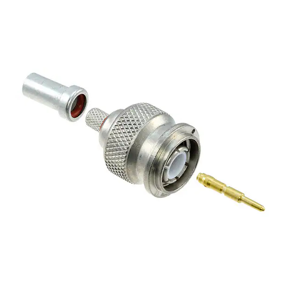
2. CRIMP END ASSEMBLY
1. Slip the ferrule on the cable, then strip the cable
and flair braid as shown in Figure 2.
2. Insert stripped conductor into the wire barrel on
the crimp end. Twist crimp end slightly to ease entry
of wire.
Plug or Jack
Crimp End
2.39
[.094]
Wire
Support
Barrel
Sleeve
Flared Braid Goes Over and
Around Support Sleeve
Crimp End Dielectric
Apply Sufficient Pressure to Cause
Cable Dielectric to Bottom Against
Dielectric of Crimp End
Cable Dielectric
Push Ferrule Over Braid, Ferrule
Bottoms Against Shoulder
Shoulder
Figure 2
©2012 Tyco Electronics Corporation, a TE Connectivity Ltd. company
All Rights Reserved
*Trademark
TE Connectivity, TE connectivity (logo), and TE (logo) are trademarks. Other logos, product and/or company names may be trademarks of their respective owners.
TNC COAXICON* Connector
Crimping Tools and Dies
BULKHEAD
JACK
JACK
331133
226484-1†
331133-1†
226484-2
Figure 1
11.13 [.438]
11.13
Braid Ferrule
[.438]
Assembly Now Ready
to be Crimped
TOOLING ASSISTANCE CENTER 1-800-722-1111
PRODUCT INFORMATION 1-800-522-6752
RIGHT-ANGLE
PLUG
1-332292-7
1-332292-8†
1-332292-9†
3. Push crimp end back under braid so that the
braid passes over and around the support sleeve.
Apply sufficient pressure to cause the cable
dielectric to bottom against the dielectric of the
crimp end. See Figure 2. Twist the crimp end
slightly to ensure bottoming.
4. Slide the ferrule forward and over the braid on the
crimp end as far as it will go. Crimp end is now
ready to be crimped. See Figure 2.
3. CRIMPING PROCEDURE
3.1. Hand Tool 69811
1. Open crimping dies by closing the tool handles
until the CERTI-CRIMP* hand crimping tool ratchet
control releases. Note that once the ratchet is
engaged, the handles cannot be opened until they
are fully closed.
2. The crimping tools have double sets of dies, see
Figure 3, to crimp the braid ferrule and wire barrel of
the jack or plug crimp end. Ferrule and wire barrel
are crimped at the same time.
3. Place the crimp end in the crimping dies as
shown in Figure 3.
Wire Barrel of Plug or
Jack Crimp End Will
Bottom in Crimping Die
Braid Ferrule Will
Bottom on Upper Braid
Ferrule Crimping Die
Figure 3
This controlled document is subject to change.
For latest revision and Regional Customer Service,
visit our website at www.te.com
Instruction Sheet
408-2235
28 SEP 12 Rev C
CRIMPING
CRIMPING
TOOL
DIES‡
69811
220006-1
1 of 2
Advertisement
Table of Contents

Related Manuals for TE Connectivity TNC COAXICON Series


Summary of Contents for TE Connectivity TNC COAXICON Series
- Page 1 All Rights Reserved PRODUCT INFORMATION 1-800-522-6752 For latest revision and Regional Customer Service, *Trademark visit our website at www.te.com TE Connectivity, TE connectivity (logo), and TE (logo) are trademarks. Other logos, product and/or company names may be trademarks of their respective owners.
- Page 2 408-2235 4. JACK AND PLUG ASSEMBLY 4. Make certain that the wire barrel and braid ferrule of the crimp end are resting firmly on the crimping 1. Assemble the jack crimp end and jack body as dies. See Figure 3. shown in Figure 6.
Need help?
Do you have a question about the TNC COAXICON Series and is the answer not in the manual?
Questions and answers